 Home
Home Back
BackSimple beam - Uniformly distributed load Calculator
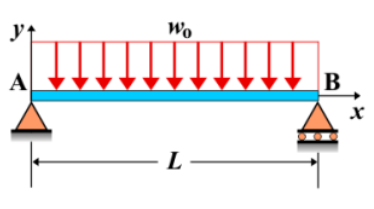
Simple Beam - Uniformly Distributed Load
A simple beam is supported at both ends, with a uniformly distributed load (UDL) applied over its entire length. This type of loading is common in structural and mechanical applications, where loads such as self-weight, snow, or evenly distributed forces act along the beam's span.
Key Concepts
- Simple Beam: A beam with supports at both ends, allowing rotation but preventing vertical displacement.
- Uniformly Distributed Load (UDL): A constant load applied per unit length along the entire span of the beam.
- Shear Force: The shear force varies linearly along the beam, with maximum values at the supports.
- Bending Moment: The bending moment is parabolic, reaching its maximum at the center of the beam.
- Deflection: The deflection is greatest at the center, forming a symmetric curve along the beam.
Behavior of the Simple Beam
- Reaction Forces:
- The total equivalent force of the UDL is its intensity multiplied by the beam length.
- The reactions at the supports are equal, each carrying half of the total load.
- Shear Force Diagram:
- The shear force decreases linearly from one support to the other.
- The maximum shear force occurs at the supports and is equal to half the total applied load.
- Bending Moment Diagram:
- The bending moment follows a parabolic shape, with a maximum at the center.
- The maximum bending moment is given by \( M_{\text{max}} = \frac{wL^2}{8} \), where \( w \) is the load intensity and \( L \) is the beam length.
- Deflection: The maximum deflection occurs at the center and is given by: \[ \delta_{\text{max}} = \frac{5wL^4}{384EI} \] where \( E \) is the modulus of elasticity and \( I \) is the moment of inertia of the beam cross-section.
Applications
- Structural Engineering: Used in floor beams, bridge spans, and roofing structures subject to uniform loads.
- Mechanical Systems: Found in conveyor belts, machine frames, and automotive chassis designs.
- Construction: Relevant for analyzing beams in buildings that carry uniform loads such as flooring, ceilings, or distributed equipment weight.
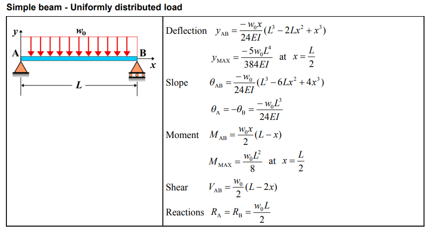
Formula
| Quantity | Formula | Notes |
|---|---|---|
| Deflection \(y_{AB}\) | \(-\frac{w_0 x}{24EI} \left(L^3 - 2Lx^2 + x^3 \right)\) | |
| Maximum Deflection \(y_{\text{MAX}}\) | \(-\frac{5w_0 L^4}{384EI}\) | At \(x = \frac{L}{2}\) |
| Slope \(\theta_{AB}\) | \(-\frac{w_0}{24EI} \left(L^3 - 6Lx^2 + 4x^3 \right)\) | |
| Maximum Slope \(\theta_A = -\theta_B\) | \(-\frac{w_0 L^3}{24EI}\) | |
| Moment \(M_{AB}\) | \(\frac{w_0 x}{2} \left(L - x \right)\) | |
| Maximum Moment \(M_{\text{MAX}}\) | \(\frac{w_0 L^2}{8}\) | At \(x = \frac{L}{2}\) |
| Shear \(V_{AB}\) | \(\frac{w_0}{2} \left(L - 2x \right)\) | |
| Reactions \(R_A = R_B\) | \(\frac{w_0 L}{2}\) |
Definitions
| Symbol | Physical quantity | Units |
|---|---|---|
| E·I | Flexural rigidity | N·m², Pa·m⁴ |
| y | Deflection or deformation | m |
| θ | Slope, Angle of rotation | - |
| x | Distance from support (origin) | m |
| L | Length of beam (without overhang) | m |
| M | Moment, Bending moment, Couple moment applied | N·m |
| P | Concentrated load, Point load, Concentrated force | N |
| w | Distributed load, Load per unit length | N/m |
| R | Reaction load, reaction force | N |
| V | Shear force, shear | N |