 Home
Home Back
BackSimple beam - Uniform load partially distributed Calculator
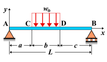
Simple Beam - Uniform Load Partially Distributed
A simple beam is supported at both ends, with a uniform load applied over a specific portion of its length. The load distribution can be anywhere along the beam, affecting the shear force, bending moment, and deflection in a distinct manner compared to a fully distributed load.
Key Concepts
- Simple Beam: A beam supported at both ends, allowing rotation but preventing vertical displacement.
- Partially Distributed Load: A uniform load covering only a section of the beam, rather than the entire span.
- Shear Force: The shear force varies depending on the position and extent of the distributed load. It changes abruptly at the points where the load begins and ends.
- Bending Moment: The bending moment is influenced by the length and location of the distributed load, reaching a maximum value somewhere along the beam.
- Deflection: The beam's deflection will be most pronounced in the loaded section, with the exact shape depending on the location and magnitude of the load.
Behavior of the Simple Beam
- Reaction Forces:
- The total equivalent force of the distributed load is its intensity multiplied by its length.
- The reactions at the supports are calculated based on equilibrium equations, considering the load's position and length.
- Shear Force Diagram:
- The shear force varies linearly in the unloaded sections and changes more noticeably within the loaded section.
- There is a discontinuity in the slope of the shear force diagram at the start and end of the distributed load.
- Bending Moment Diagram:
- The bending moment increases within the loaded region, reaching a peak depending on the load’s position and length.
- The moment diagram has different slopes before, within, and after the loaded section.
- Deflection: The deflection is most pronounced in the region affected by the distributed load. The exact value depends on the beam's material, cross-section, and load parameters.
Applications
- Structural Engineering: Used in bridge and floor beam designs where loads are applied over partial spans.
- Mechanical Systems: Found in machine components subject to localized loading, such as conveyor systems.
- Construction: Relevant for analyzing beams subjected to unevenly distributed loads from walls, roofing, or storage.
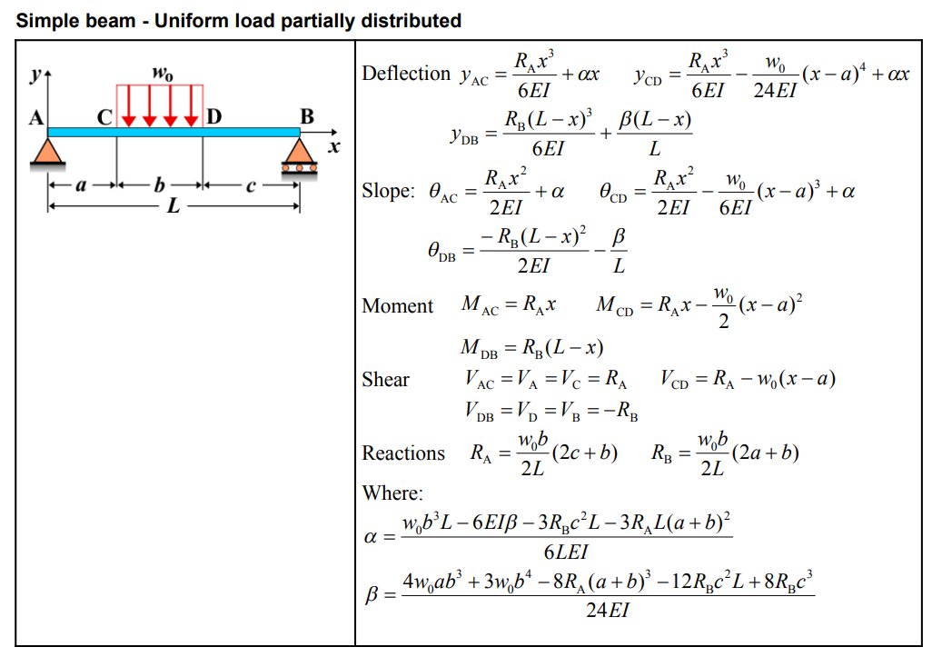
Formula
| Quantity | Formula |
|---|---|
| Deflection \(y_{AC}\) | \(\frac{R_{A}x^{3}}{6EI} + \alpha x\) |
| Deflection \(y_{CD}\) | \(\frac{R_{A}x^{3}}{6EI} - \frac{w_{0}}{24EI}(x-a)^{4} + \alpha x\) |
| Deflection \(y_{DB}\) | \(\frac{R_{B}(L-x)^{3}}{6EI} + \frac{\beta (L-x)}{L}\) |
| Slope \(\theta_{AC}\) | \(\frac{R_{A}x^{2}}{2EI} + \alpha\) |
| Slope \(\theta_{CD}\) | \(\frac{R_{A}x^{2}}{2EI} - \frac{w_{0}}{6EI}(x-a)^{3} + \alpha\) |
| Slope \(\theta_{DB}\) | \(\frac{-R_{B}(L-x)^{2}}{2EI} - \frac{\beta}{L}\) |
| Moment \(M_{AC}\) | \(R_{A} x\) |
| Moment \(M_{CD}\) | \(R_{A} x - \frac{w_{0}}{2}(x-a)^{2}\) |
| Moment \(M_{DB}\) | \(R_{B}(L-x)\) |
| Shear \(V_{AC}, V_{A}, V_{C}\) | \(R_{A}\) |
| Shear \(V_{CD}\) | \(R_{A} - w_{0}(x-a)\) |
| Shear \(V_{DB}, V_{D}, V_{B}\) | \(-R_{B}\) |
| Reaction \(R_{A}\) | \(\frac{w_{0}b}{2L}(2c+b)\) |
| Reaction \(R_{B}\) | \(\frac{w_{0}b}{2L}(2a+b)\) |
| \(\alpha\) | \(\frac{w_{0}b^{3}L - 6EI\beta - 3R_{B}c^{2}L - 3R_{A}L(a+b)^{2}}{6LEI}\) |
| \(\beta\) | \(\frac{4w_{0}ab^{3} + 3w_{0}b^{4} - 8R_{A}(a+b)^{3} - 12R_{B}c^{2}L + 8R_{B}c^{3}}{24EI}\) |
Definitions
| Symbol | Physical quantity | Units |
|---|---|---|
| E·I | Flexural rigidity | N·m², Pa·m⁴ |
| y | Deflection or deformation | m |
| θ | Slope, Angle of rotation | - |
| x | Distance from support (origin) | m |
| L | Length of beam (without overhang) | m |
| M | Moment, Bending moment, Couple moment applied | N·m |
| P | Concentrated load, Point load, Concentrated force | N |
| w | Distributed load, Load per unit length | N/m |
| R | Reaction load, reaction force | N |
| V | Shear force, shear | N |