 Home
Home Back
BackSimple beam - Uniform load partially distributed at left end (II) Calculator
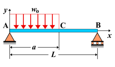
Simple Beam - Uniform Load Partially Distributed at Left End (II)
A simple beam is supported at both ends, with a uniform load partially distributed at the left end of the beam. In this case, the uniform load applies over a specific length starting from the left support, but it extends to a different length compared to the previous scenario. This load distribution affects the shear force, bending moment, and deflection along the beam in a way similar to the first case, but with different magnitude and distribution characteristics.
Key Concepts
- Simple Beam: A beam supported at both ends, with no intermediate supports.
- Uniform Load: A distributed load that is constant along the length it covers. In this case, it is applied at the left end and extends partially along the beam, covering a longer length than in the previous case.
- Shear Force: The shear force is greatest near the left support, where the load is applied. As you move away from the left support, the shear force gradually decreases along the length of the load distribution.
- Bending Moment: The bending moment is highest near the left support and decreases along the length of the beam. The bending moment diagram will show the variation as a result of the length of the load distribution and its intensity.
- Deflection: The deflection will be greatest near the left support and decrease as you move toward the right end. The deflection curve will be steeper in the region where the load is applied.
Behavior of the Simple Beam
- Reaction Forces:
- The total load applied at the left end is the product of the load intensity and the length of the distribution. The reactions at both supports are determined by equilibrium conditions. Since the load is applied over a larger portion of the beam than in the previous case, the reactions at both ends will differ.
- Shear Force Diagram:
- The shear force diagram will show a linear variation along the beam. The shear force is maximum at the left support and decreases as you move along the length of the load distribution. The decrease in shear force will be more gradual compared to the previous case due to the longer load distribution.
- Bending Moment Diagram:
- The bending moment is highest at the left support and decreases as you move along the beam. The bending moment diagram will show a curve that reflects the length of the load distribution. The area under the shear force diagram can be used to calculate the bending moment at any point along the beam.
- Deflection: The deflection is greatest at the left end where the load is applied. The magnitude of the deflection at the free end will be influenced by the length of the load distribution and the intensity of the applied load.
Applications
- Structural Engineering: This type of loading is commonly encountered in structural design, especially for beams subjected to localized loads that extend over part of the beam's length, such as in bridges or buildings with concentrated loads near supports.
- Mechanical Systems: Used in mechanical components such as supports for machines or equipment that experience localized loading along a portion of their length.
- Construction: Relevant in the analysis of beams, such as those used in flooring systems, cantilevers, or bridges where the load is applied over a specific length close to one of the supports.
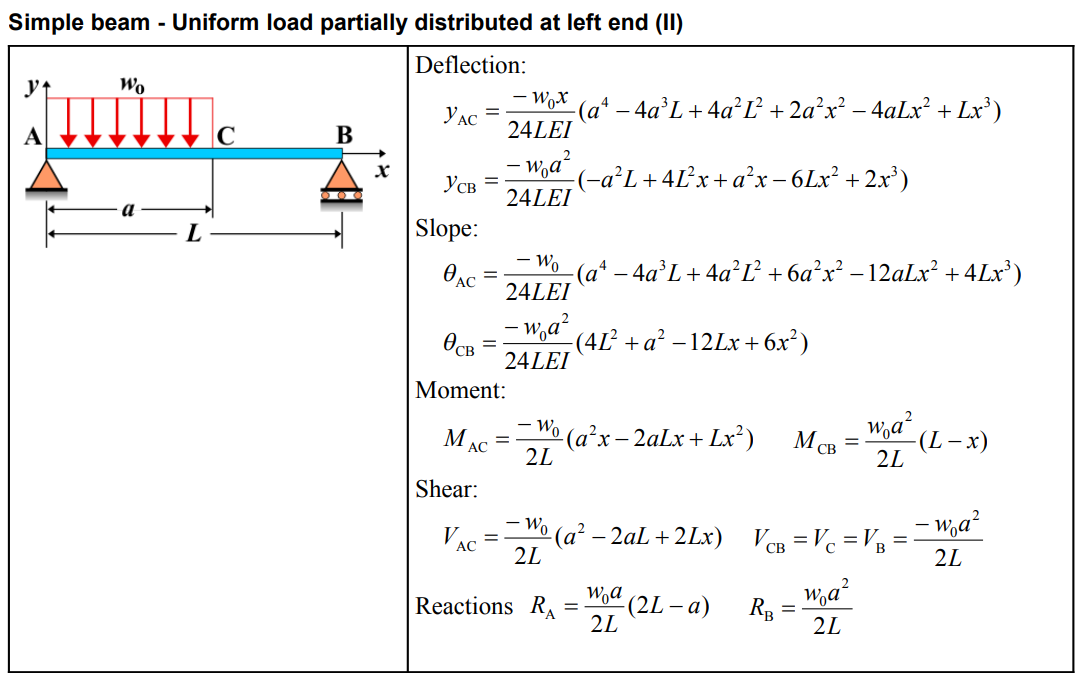
Formula
| Quantity | Formula |
|---|---|
| Deflection \(y_{AC}\) | \(-\frac{w_0 x}{24LEI} \left(a^4 - 4a^3L + 4a^2L^2 + 2a^2x^2 - 4aLx^2 + Lx^3 \right)\) |
| Deflection \(y_{CB}\) | \(-\frac{w_0 a^2}{24LEI} \left(-a^2L + 4L^2x + a^2x - 6Lx^2 + 2x^3 \right)\) |
| Slope \(\theta_{AC}\) | \(-\frac{w_0}{24LEI} \left(a^4 - 4a^3L + 4a^2L^2 + 6a^2x^2 - 12aLx^2 + 4Lx^3 \right)\) |
| Slope \(\theta_{CB}\) | \(-\frac{w_0 a^2}{24LEI} \left(4L^2 - 12Lx + 6x^2 \right)\) |
| Moment \(M_{AC}\) | \(-\frac{w_0}{2L} \left(a^2x - 2aLx + Lx^2 \right)\) |
| Moment \(M_{CB}\) | \(\frac{w_0 a^2}{2L} \left(L - x \right)\) |
| Shear \(V_{AC}\) | \(-\frac{w_0}{2L} \left(a^2 - 2aL + 2Lx \right)\) |
| Shear \(V_{CB} = V_C = V_B\) | \(-\frac{w_0 a^2}{2L}\) |
| Reactions \(R_A\) | \(\frac{w_0 a}{2L} \left(2L - a \right)\) |
| Reactions \(R_B\) | \(\frac{w_0 a^2}{2L}\) |
Definitions
| Symbol | Physical quantity | Units |
|---|---|---|
| E·I | Flexural rigidity | N·m², Pa·m⁴ |
| y | Deflection or deformation | m |
| θ | Slope, Angle of rotation | - |
| x | Distance from support (origin) | m |
| L | Length of beam (without overhang) | m |
| M | Moment, Bending moment, Couple moment applied | N·m |
| P | Concentrated load, Point load, Concentrated force | N |
| w | Distributed load, Load per unit length | N/m |
| R | Reaction load, reaction force | N |
| V | Shear force, shear | N |