 Home
Home Back
BackSimple beam - Uniform load partially distributed at each end Calculator
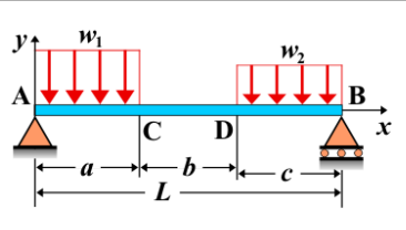
Simple Beam - Uniform Load Partially Distributed at Each End
A simple beam is supported at both ends, with a uniform load partially distributed at each end of the beam. This means that the load is applied over a specific portion of the beam near each support, rather than being spread across the entire length of the beam. The distribution of the load influences the shear force, bending moment, and deflection along the beam.
Key Concepts
- Simple Beam: A beam supported at both ends, with no intermediate supports.
- Uniform Load: A distributed load that is constant over the length it covers. In this case, the load is uniformly distributed at each end of the beam.
- Shear Force: The shear force varies along the beam. At the supports, the shear force is influenced by the total load applied to the beam and its distribution at the ends. The shear force will gradually decrease as you move away from the supports.
- Bending Moment: The bending moment is greatest at the supports and decreases along the length of the beam. The bending moment at the supports will be influenced by the magnitude and length of the uniform loads distributed at each end.
- Deflection: The deflection is greatest at the center of the beam and is influenced by the distribution of the applied loads. The closer the load is applied to the supports, the smaller the deflection will be at the free end.
Behavior of the Simple Beam
- Reaction Forces:
- The total load on the beam is the sum of the uniformly distributed loads at each end. The reactions at the supports are calculated by using equilibrium conditions for vertical forces and moments. The reactions will not be equal, as the loads are not distributed symmetrically.
- Shear Force Diagram:
- The shear force diagram will show a variation that is influenced by the distribution of the load at each end. The shear force will start at its maximum value at the supports and decrease linearly along the length of the load distribution.
- Bending Moment Diagram:
- The bending moment diagram will be shaped based on the load distribution. It will have maximum moments at the supports, with the magnitude decreasing as you move towards the center of the beam.
- Deflection: The deflection is largest at the center of the beam and is determined by the load distribution and the stiffness of the beam. The deflection is influenced by the length of the load application and the beam’s material properties.
Applications
- Structural Engineering: Common in beams with localized loading, such as in bridges or buildings where loads are concentrated near the supports.
- Mechanical Systems: Found in mechanical systems where parts are subjected to loads over specific regions, such as conveyor belts or supports for machinery.
- Construction: Often used in the analysis of cantilevered or simply supported beams where the load distribution is not uniform over the entire length, such as in floor beams or roof trusses.
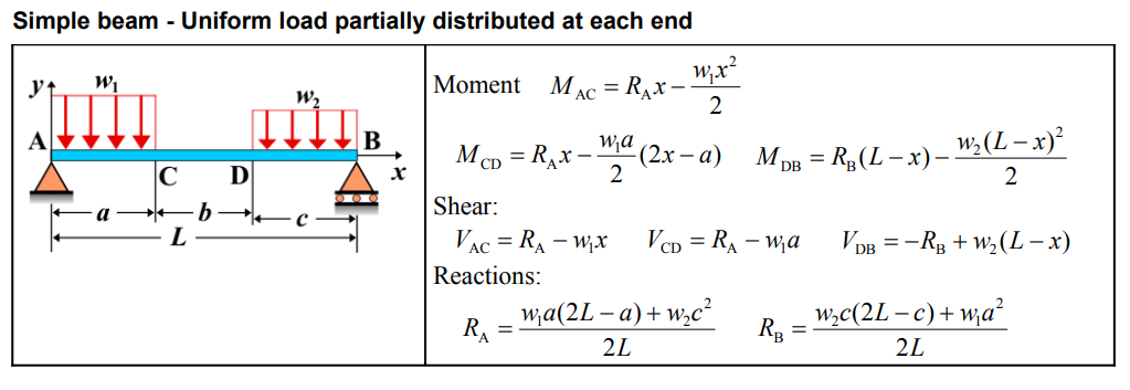
Formula
| Quantity | Formula |
|---|---|
| Moment \(M_{AC}\) | \(R_{A} x - \frac{w_{1}x^{2}}{2}\) |
| Moment \(M_{CD}\) | \(R_{A} x - \frac{w_{1}a}{2}(2x-a)\) |
| Moment \(M_{DB}\) | \(R_{B}(L-x) - \frac{w_{2}(L-x)^{2}}{2}\) |
| Shear \(V_{AC}\) | \(R_{A} - w_{1} x\) |
| Shear \(V_{CD}\) | \(R_{A} - w_{1} a\) |
| Shear \(V_{DB}\) | \(-R_{B} + w_{2}(L-x)\) |
| Reaction \(R_{A}\) | \(\frac{w_{1}a(2L-a) + w_{2}c^{2}}{2L}\) |
| Reaction \(R_{B}\) | \(\frac{w_{2}c(2L-c) + w_{1}a^{2}}{2L}\) |
Definitions
| Symbol | Physical quantity | Units |
|---|---|---|
| E·I | Flexural rigidity | N·m², Pa·m⁴ |
| y | Deflection or deformation | m |
| θ | Slope, Angle of rotation | - |
| x | Distance from support (origin) | m |
| L | Length of beam (without overhang) | m |
| M | Moment, Bending moment, Couple moment applied | N·m |
| P | Concentrated load, Point load, Concentrated force | N |
| w | Distributed load, Load per unit length | N/m |
| R | Reaction load, reaction force | N |
| V | Shear force, shear | N |