 Home
Home Back
BackSimple beam - Two equal couple moments Mo at each end Calculator
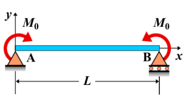
Simple Beam - Two Equal Couple Moments Mo at Each End
A simple beam is supported at both ends, with two equal couple moments \( M_o \) applied at each end. These moments create a bending effect along the beam but do not affect the shear force distribution. Since the couple moments are applied at the supports, they induce purely bending moments, which affect the beam's curvature and deflection.
Key Concepts
- Simple Beam: A beam supported at both ends, with no intermediate supports.
- Couple Moments: A couple is a pair of equal and opposite forces acting at a distance, creating a moment. In this case, two equal couple moments are applied at each end of the beam.
- Shear Force: Since the applied loads are couple moments, there is no shear force induced along the beam. The shear force is zero at all points.
- Bending Moment: The bending moment is constant along the beam, as it is determined by the applied couple moments at the ends. The moment at any point along the beam is equal to the applied couple moment at the support.
- Deflection: The deflection of the beam is influenced by the bending moment. The maximum deflection will occur at the midpoint of the beam, but it is determined by the magnitude of the applied couple moments and the beam's stiffness.
Behavior of the Simple Beam
- Reaction Forces:
- The applied couple moments at each support do not result in vertical reactions but create rotational effects at the ends. These moments produce a constant bending moment along the beam.
- Shear Force Diagram:
- Since there are no vertical loads acting on the beam, the shear force remains zero at all points along the length of the beam.
- Bending Moment Diagram:
- The bending moment is constant along the length of the beam, equal to the applied couple moment at each support. The moment diagram is a horizontal line equal to \( M_o \) at all points along the beam.
- Deflection: The deflection is a result of the constant bending moment. The maximum deflection occurs at the midpoint of the beam and can be calculated using standard deflection formulas for beams with constant bending moments.
Applications
- Structural Engineering: Couple moments are often used in the analysis of beams in structures where rotational effects at the supports are known, such as in frames or joints with moment connections.
- Mechanical Systems: Applied in systems where two opposing moments are required, such as in mechanical linkages or rotating equipment where no net force is applied but a moment is needed to maintain equilibrium.
- Construction: Relevant in the analysis of structural beams where rotational moments are introduced at the supports, common in building or bridge design where moment-resisting frames are used.
Formula
| Quantity | Formula |
|---|---|
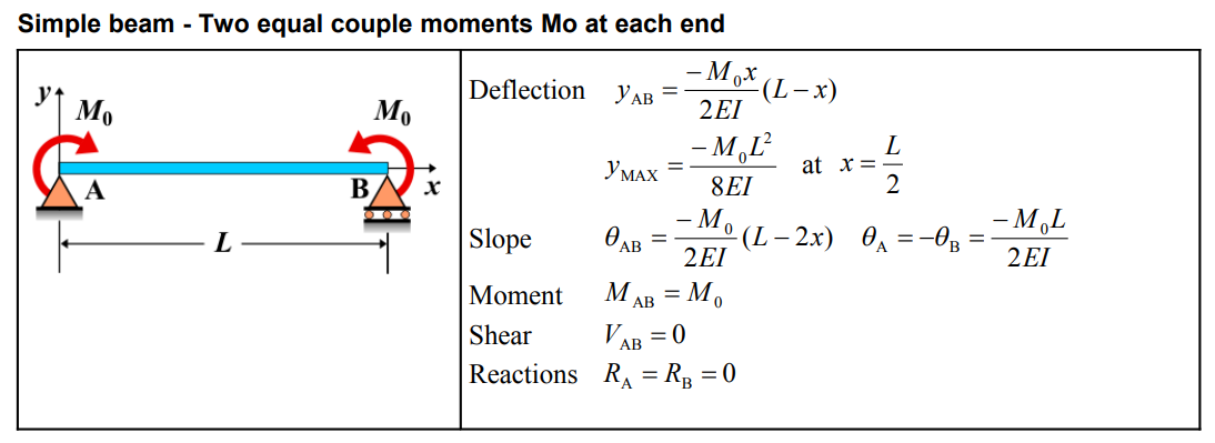
| Deflection \(y_{AB}\) | \(\frac{-M_{0}x}{2EI}(L-x)\) |
| Maximum Deflection \(y_{\text{MAX}}\) | \(\frac{-M_{0}L^{2}}{8EI} \, \text{at} \, x = \frac{L}{2}\) |
| Slope \(\theta_{AB}\) | \(\frac{-M_{0}}{2EI}(L-2x)\) |
| Slope \(\theta_{A}, \theta_{B}\) | \(\theta_{A} = -\theta_{B} = \frac{-M_{0}L}{2EI}\) |
| Moment \(M_{AB}\) | \(M_{0}\) |
| Shear \(V_{AB}\) | 0 |
| Reactions \(R_{A}, R_{B}\) | \(R_{A} = R_{B} = 0\) |
Definitions
| Symbol | Physical quantity | Units |
|---|---|---|
| E·I | Flexural rigidity | N·m², Pa·m⁴ |
| y | Deflection or deformation | m |
| θ | Slope, Angle of rotation | - |
| x | Distance from support (origin) | m |
| L | Length of beam (without overhang) | m |
| M | Moment, Bending moment, Couple moment applied | N·m |
| P | Concentrated load, Point load, Concentrated force | N |
| w | Distributed load, Load per unit length | N/m |
| R | Reaction load, reaction force | N |
| V | Shear force, shear | N |