 Home
Home Back
BackSimple beam - Two equal concentrated loads unsymmetrically placed Calculator
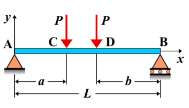
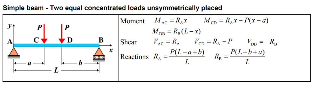
Simple Beam - Two Equal Concentrated Loads Unsymmetrically Placed
A simple beam is supported at both ends, with two equal concentrated loads applied unsymmetrically along its length. Unlike the symmetric placement, these loads are located at different distances from the supports. The unsymmetrical positioning of the loads leads to an uneven distribution of shear forces and bending moments along the beam.
Key Concepts
- Simple Beam: A beam supported at both ends, with no intermediate supports.
- Concentrated Loads: Point loads applied at specific locations along the beam. In this case, two equal loads are placed at unequal distances from the supports.
- Shear Force: The shear force is non-symmetrical and varies more significantly along the beam. It is maximum at the supports and decreases in a non-linear fashion as you move towards the middle of the beam, where the load intensities are unequal.
- Bending Moment: The bending moment is non-symmetrical as well, with the maximum moment occurring near the loads and different at both ends of the beam. It is affected by the unsymmetrical load placement.
- Deflection: The deflection is also non-symmetrical, with the maximum deflection occurring somewhere between the two loads, not at the center of the beam.
Behavior of the Simple Beam
- Reaction Forces:
- The total load on the beam is the sum of the two concentrated loads. The reactions at the supports are determined by summing the vertical forces and considering equilibrium of moments. Due to the unsymmetrical load placement, the reactions at the supports will not be equal.
- Shear Force Diagram:
- The shear force diagram is uneven, with the shear force at one support being greater than the other. The diagram shows a non-linear variation of shear along the beam, with the magnitude depending on the distance from the loads to the supports.
- Bending Moment Diagram:
- The bending moment diagram will show a non-symmetrical distribution, with higher moments at locations closer to the loads. The maximum bending moment will occur closer to the larger load, and the values decrease as you move towards the other support.
- Deflection: The deflection is not symmetric and is generally greatest between the two loads. The exact location of maximum deflection can be calculated using deflection formulas that take into account the distances of the loads from the supports.
Applications
- Structural Engineering: This type of loading is encountered in situations where two loads are applied at different distances, such as in beams supporting unevenly distributed equipment or machinery.
- Mechanical Systems: Found in mechanical parts where forces are applied unevenly, such as shafts or beams subjected to point forces from equipment placed at different locations.
- Construction: Common in the analysis of beams where the loads applied to the structure are not symmetrically placed, such as in bridges or buildings with uneven load distributions.
Formula
Definitions
| Symbol | Physical quantity | Units |
|---|---|---|
| E·I | Flexural rigidity | N·m², Pa·m⁴ |
| y | Deflection or deformation | m |
| θ | Slope, Angle of rotation | - |
| x | Distance from support (origin) | m |
| L | Length of beam (without overhang) | m |
| M | Moment, Bending moment, Couple moment applied | N·m |
| P | Concentrated load, Point load, Concentrated force | N |
| w | Distributed load, Load per unit length | N/m |
| R | Reaction load, reaction force | N |
| V | Shear force, shear | N |