 Home
Home Back
BackSimple beam - Two equal concentrated loads unsymmetrically placed II Calculator
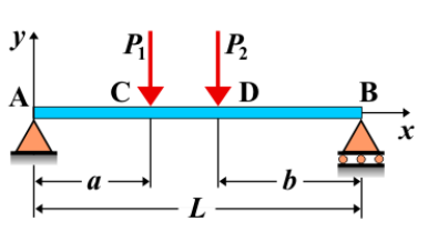
Simple Beam - Two Unequal Concentrated Loads Unsymmetrically Placed II
A simple beam is supported at both ends, with two unequal concentrated loads applied unsymmetrically along its length. These loads are not only unequal in magnitude but are also placed at different distances from the supports. This results in an asymmetric distribution of shear forces, bending moments, and deflections along the beam. The behavior of the beam is affected by the positions and magnitudes of the loads.
Key Concepts
- Simple Beam: A beam supported at both ends, with no intermediate supports.
- Unequal Concentrated Loads: Point loads of different magnitudes applied at different locations along the beam. The position and magnitude of each load influence the beam’s response.
- Shear Force: The shear force is non-symmetrical and varies depending on the position of the loads. It is influenced by the relative distances from the supports and the magnitude of the loads.
- Bending Moment: The bending moment diagram is uneven, with the maximum moments occurring near the loads and varying based on the load distribution and distance from the supports.
- Deflection: The deflection is also non-symmetrical, with the maximum deflection occurring somewhere between the two loads. Its magnitude and location depend on the relative sizes and positions of the loads.
Behavior of the Simple Beam
- Reaction Forces:
- The total load on the beam is the sum of the two concentrated loads. The reactions at the supports are determined by using equilibrium conditions for both vertical forces and moments. Due to the unsymmetrical and unequal nature of the loads, the reactions at the supports will not be equal.
- Shear Force Diagram:
- The shear force diagram is non-symmetrical, with varying shear forces at different points along the beam. The magnitude of shear depends on the positions and magnitudes of the unequal loads, with larger shear forces closer to the larger loads.
- Bending Moment Diagram:
- The bending moment diagram shows non-symmetrical moments, with larger moments occurring closer to the larger load. The maximum bending moment may occur either under one of the loads or somewhere between the loads, depending on the distances and magnitudes of the forces.
- Deflection: The deflection is non-symmetrical, with the maximum deflection occurring closer to the larger load. The location and magnitude of deflection depend on the relative positions and magnitudes of the loads.
Applications
- Structural Engineering: This type of loading is encountered in situations where point loads of unequal magnitude are applied at different points along a beam, such as in bridges or buildings with uneven loading conditions.
- Mechanical Systems: Found in mechanical components subjected to unequal point loads, such as beams in machinery or structural supports for unevenly distributed equipment.
- Construction: Relevant in the analysis of beams where loads are unevenly placed, such as in bridges or floors subjected to point loads that vary in size and position.
Formula
| Quantity | Formula |
|---|---|
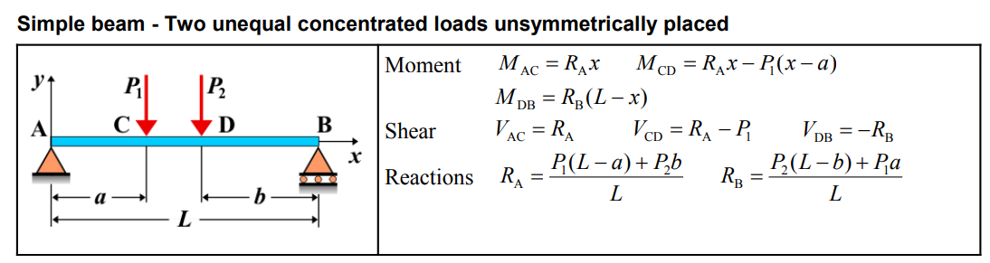
| Moment \(M_{CD}\) | \(M_{CD} = R_{A} \cdot x - P_{1} \cdot (x - a)\) |
| Moment \(M_{DB}\) | \(M_{DB} = R_{B} \cdot (L - x)\) |
| Shear \(V_{AC}\) | \(V_{AC} = R_{A}\) |
| Shear \(V_{CD}\) | \(V_{CD} = R_{A} - P_{1}\) |
| Shear \(V_{DB}\) | \(V_{DB} = -R_{B}\) |
| Reaction \(R_{A}\) | \(R_{A} = \frac{P_{1}(L - a) + P_{2}b}{L}\) |
| Reaction \(R_{B}\) | \(R_{B} = \frac{P_{2}(L - b) + P_{1}a}{L}\) |
Definitions
| Symbol | Physical quantity | Units |
|---|---|---|
| E·I | Flexural rigidity | N·m², Pa·m⁴ |
| y | Deflection or deformation | m |
| θ | Slope, Angle of rotation | - |
| x | Distance from support (origin) | m |
| L | Length of beam (without overhang) | m |
| M | Moment, Bending moment, Couple moment applied | N·m |
| P | Concentrated load, Point load, Concentrated force | N |
| w | Distributed load, Load per unit length | N/m |
| R | Reaction load, reaction force | N |
| V | Shear force, shear | N |