 Home
Home Back
BackSimple beam - Two equal concentrated loads symmetrically placed Calculator
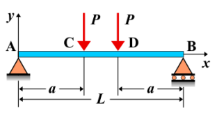
Simple Beam - Two Equal Concentrated Loads Symmetrically Placed
A simple beam is supported at both ends, with two equal concentrated loads applied symmetrically along its length. These loads are placed at equal distances from the beam's center, resulting in a symmetric load distribution. The loads create shear forces and bending moments that are symmetrically distributed along the length of the beam.
Key Concepts
- Simple Beam: A beam supported at both ends, with no intermediate supports.
- Concentrated Loads: Point loads applied at specific locations along the beam. In this case, two equal loads are placed symmetrically along the beam.
- Shear Force: The shear force varies along the beam and is maximum at the supports. It decreases towards the center, where the loads are applied symmetrically.
- Bending Moment: The bending moment follows a symmetric pattern, with maximum moments occurring under the loads and at the supports.
- Deflection: The deflection of the beam will be symmetric, with maximum deflection occurring between the two loads, at the center of the beam.
Behavior of the Simple Beam
- Reaction Forces:
- The total load is the sum of the two concentrated loads. The reactions at the supports can be determined by summing vertical forces and applying equilibrium conditions. Since the loads are symmetrically placed, the reaction forces at each support will be equal.
- Shear Force Diagram:
- The shear force starts at a maximum value at the left support and decreases linearly towards the center of the beam. It then increases symmetrically as the load is approached, with a value of zero at the midpoint between the two loads.
- Bending Moment Diagram:
- The bending moment increases from zero at the left support, reaches a maximum value under each load, and then decreases to zero at the right support. The moment diagram is symmetric about the center of the beam.
- Deflection: The deflection is symmetric along the length of the beam, with the maximum deflection occurring at the midpoint between the two loads. The deflection can be calculated using standard deflection formulas for symmetric loading conditions.
Applications
- Structural Engineering: This type of loading is common in structures such as bridges or buildings, where evenly distributed point loads are applied to the beam.
- Mechanical Systems: Found in machine parts or components that are subjected to two symmetrical point forces.
- Construction: Used in the analysis of beams in buildings or bridges where loads are applied symmetrically across the structure, such as in floor systems or beams supporting machinery.
Formula
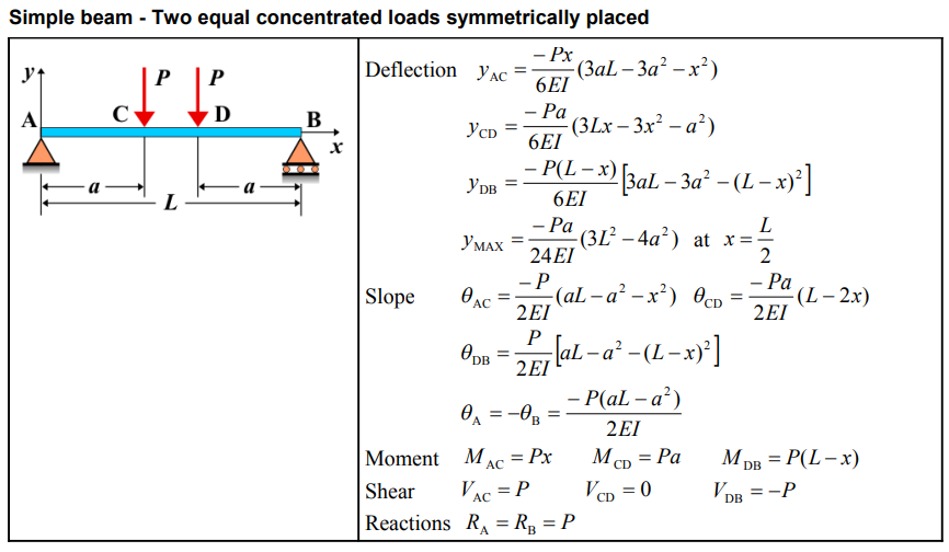
Definitions
| Symbol | Physical quantity | Units |
|---|---|---|
| E·I | Flexural rigidity | N·m², Pa·m⁴ |
| y | Deflection or deformation | m |
| θ | Slope, Angle of rotation | - |
| x | Distance from support (origin) | m |
| L | Length of beam (without overhang) | m |
| M | Moment, Bending moment, Couple moment applied | N·m |
| P | Concentrated load, Point load, Concentrated force | N |
| w | Distributed load, Load per unit length | N/m |
| R | Reaction load, reaction force | N |
| V | Shear force, shear | N |