 Home
Home Back
BackSimple beam - Load increasing uniformly to right end Calculator
Simple Beam - Load Increasing Uniformly to Right End
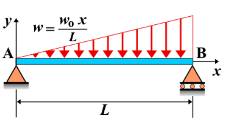
A simple beam is supported at both ends, with a distributed load that increases uniformly from the left support to the right support. The load intensity starts from zero at the left end and increases linearly to a maximum value at the right end. This loading condition creates varying shear force and bending moment along the beam's length, with the intensity of both increasing as the load increases towards the right support.
Key Concepts
- Simple Beam: A beam supported at both ends, with no intermediate supports.
- Linearly Increasing Load: The load intensity starts from zero at the left support and increases linearly to a maximum value at the right support.
- Shear Force: The shear force varies along the beam. It starts at zero at the left end, increases as the load increases, and reaches its maximum value at the right support.
- Bending Moment: The bending moment increases from zero at the left support, reaching its maximum value at the right support, where the load intensity is highest.
- Deflection: The maximum deflection occurs closer to the right support, where the bending moment is greatest. The deflection shape follows the curve of the load distribution.
Behavior of the Simple Beam
- Reaction Forces:
- The total load on the beam can be calculated by finding the area under the load distribution. The reactions at the supports are determined by summing the vertical forces and considering the equilibrium of moments.
- Shear Force Diagram:
- The shear force starts at zero at the left support, increases along the beam as the load increases, and reaches its maximum value at the right support.
- Bending Moment Diagram:
- The bending moment increases quadratically along the length of the beam, reaching its maximum value at the right support, where the load intensity is greatest.
- Deflection: The deflection is maximum at the right support, where the bending moment is greatest. The deflection can be calculated using beam deflection formulas that depend on the beam’s length, the load distribution, and material properties.
Applications
- Structural Engineering: This type of loading is common in structures subjected to loads that increase from one side to the other, such as beams subjected to increasing wind pressure or soil pressure.
- Mechanical Systems: Found in components experiencing variable loading that increases towards one end, such as shafts or rods with forces applied that increase from left to right.
- Construction: Used in the analysis of beams in buildings and other structures where loads increase toward one support, such as beams in bridges or elevated floors.
Formula
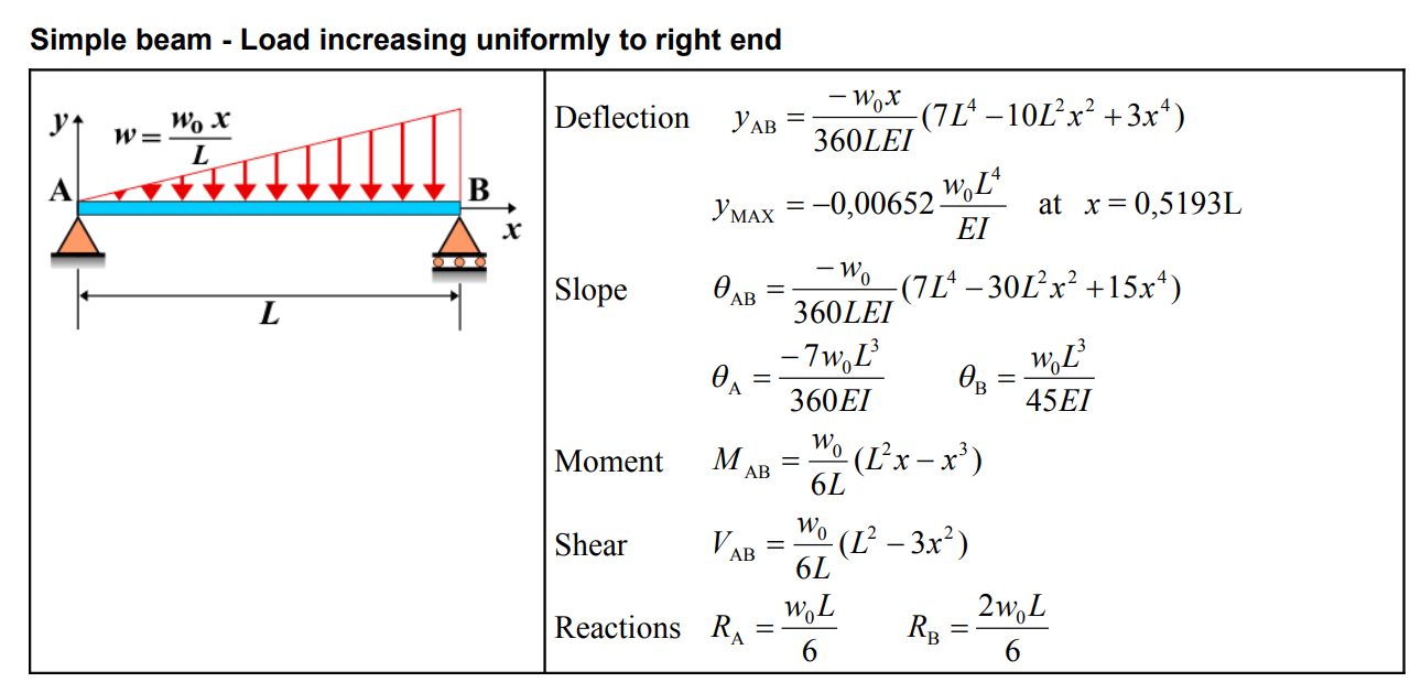
| Deflection (AB) | \[ y_{\mathrm{AB}} = \frac{-w_{0} x}{360 L E I}\left(7 L^{4}-10 L^{2} x^{2}+3 x^{4}\right) \] |
| Maximum Deflection | \[ y_{\mathrm{MAX}} = -0.00652 \frac{w_{0} L^{4}}{E I} \quad \text{at} \quad x = 0.5193 L \] |
| Slope (AB) | \[ \theta_{\mathrm{AB}} = \frac{-w_{0}}{360 L E I}\left(7 L^{4}-30 L^{2} x^{2}+15 x^{4}\right) \] |
| Slope (A and B) | \[ \theta_{\mathrm{A}} = \frac{-7 w_{0} L^{3}}{360 E I} \quad \theta_{\mathrm{B}} = \frac{w_{0} L^{3}}{45 E I} \] |
| Moment (AB) | \( M_{\mathrm{AB}} = \frac{w_{0}}{6 L}\left(L^{2} x - x^{3}\right) \) |
| Shear (AB) | \[ V_{\mathrm{AB}} = \frac{w_{0}}{6 L}\left(L^{2}-3 x^{2}\right) \] |
| Reactions | \( R_{\mathrm{A}} = \frac{w_{0} L}{6} \quad R_{\mathrm{B}} = \frac{2 w_{0} L}{6} \) |
Definitions
| Symbol | Physical quantity | Units |
|---|---|---|
| E·I | Flexural rigidity | N·m², Pa·m⁴ |
| y | Deflection or deformation | m |
| θ | Slope, Angle of rotation | - |
| x | Distance from support (origin) | m |
| L | Length of beam (without overhang) | m |
| M | Moment, Bending moment, Couple moment applied | N·m |
| P | Concentrated load, Point load, Concentrated force | N |
| w | Distributed load, Load per unit length | N/m |
| R | Reaction load, reaction force | N |
| V | Shear force, shear | N |