 Home
Home Back
BackSimple beam - Couple moments M1 and M2 at each end II Calculator
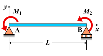
Simple Beam - Couple Moments M1 and M2 at Each End II
A simple beam is supported at both ends, with couple moments \( M_1 \) and \( M_2 \) applied at each end. These moments induce rotational effects at each support, causing bending moments along the length of the beam. The couple moments applied at both ends result in an internal moment distribution that varies along the beam. The combined effect of these moments influences the shear force and deflection profiles as well.
Key Concepts
- Simple Beam: A beam supported at both ends, with no intermediate supports.
- Couple Moment M1 at Left End: A couple moment \( M_1 \) applied at the left end creates a rotational effect at the left support.
- Couple Moment M2 at Right End: A couple moment \( M_2 \) applied at the right end creates a rotational effect at the right support.
- Shear Force: While the couple moments themselves do not directly affect the shear force, their influence on the internal moment distribution can lead to varying shear forces along the beam.
- Bending Moment: The bending moment diagram is influenced by the couple moments applied at both ends, with the moments distributed along the beam resulting in internal moments and bending.
- Deflection: The deflection of the beam is determined by the magnitudes of the couple moments, the beam's length, and its material properties. Deflection will vary based on the combined effect of the two couple moments.
Behavior of the Simple Beam
- Reaction Forces:
- The reaction forces at the supports are calculated using equilibrium equations, taking into account the couple moments \( M_1 \) and \( M_2 \). These moments result in balancing forces at the supports to maintain equilibrium.
- Shear Force Diagram:
- The shear force diagram may be nonuniform due to the varying internal moments created by \( M_1 \) and \( M_2 \). These moments do not directly create shear forces but affect the beam’s internal behavior.
- Bending Moment Diagram:
- The bending moment diagram for this loading condition will show two distinct moments, one from \( M_1 \) at the left end and one from \( M_2 \) at the right end. These moments combine along the length of the beam, resulting in an internal moment distribution.
- Deflection: The deflection of the beam is influenced by the combination of the couple moments. The beam will deflect differently depending on the magnitudes of \( M_1 \) and \( M_2 \) and the material properties of the beam.
Applications
- Structural Engineering: Couple moments at the ends of a simple beam are useful in modeling structures subjected to twisting or rotational forces, such as frames and beams with end supports experiencing torsion.
- Construction: The application of couple moments at both ends of a beam is common in the analysis of beams subjected to rotational forces, often encountered in framed structures or cantilevered systems.
- Mechanical Systems: These couple moments can also represent the forces in mechanical systems, such as rotating shafts, where torsional or rotational forces occur at the ends of the beam or component.
Formula
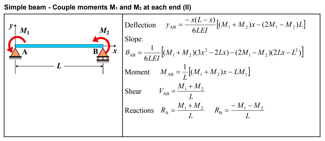
| Deflection (AB) | \( y_{\mathrm{AB}} = \frac{-x(L-x)}{6 L E I}\left[\left(M_1+M_2\right) x-\left(2 M_1-M_2\right) L\right] \) |
| Slope (AB) | \[ \theta_{\mathrm{AB}} = \frac{1}{6 L E I}\left[\left(M_1+M_2\right)\left(3 x^2-2 L x\right)-\left(2 M_1-M_2\right)\left(2 L x-L^2\right)\right] \] |
| Moment (AB) | \( M_{\mathrm{AB}} = \frac{1}{L}\left[\left(M_1+M_2\right) x-L M_1\right] \) |
| Shear (AB) | \( V_{\mathrm{AB}} = \frac{M_1+M_2}{L} \) |
| Reactions | \( R_{\mathrm{A}} = \frac{M_1+M_2}{L} \quad R_{\mathrm{B}} = \frac{-M_1-M_2}{L} \) |
Definitions
| Symbol | Physical quantity | Units |
|---|---|---|
| E·I | Flexural rigidity | N·m², Pa·m⁴ |
| y | Deflection or deformation | m |
| θ | Slope, Angle of rotation | - |
| x | Distance from support (origin) | m |
| L | Length of beam (without overhang) | m |
| M | Moment, Bending moment, Couple moment applied | N·m |
| P | Concentrated load, Point load, Concentrated force | N |
| w | Distributed load, Load per unit length | N/m |
| R | Reaction load, reaction force | N |
| V | Shear force, shear | N |