 Home
Home Back
BackSimple beam - Couple moments M1 and M2 at each end I Calculator
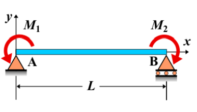
Simple Beam - Couple Moments M1 and M2 at Each End I
A simple beam is supported at both ends, with two couple moments \( M_1 \) and \( M_2 \) applied at each end of the beam. These couple moments create rotational effects at the beam's supports, leading to bending moments and potentially shear forces along the beam. The application of two couple moments causes a nonuniform bending moment distribution across the beam's length.
Key Concepts
- Simple Beam: A beam supported at both ends, with no intermediate supports.
- Couple Moment M1 at Left End: A couple moment \( M_1 \) applied at the left end of the beam, causing a rotational effect at that support.
- Couple Moment M2 at Right End: A couple moment \( M_2 \) applied at the right end of the beam, creating a rotational effect at that support.
- Shear Force: The shear force may not be zero along the length of the beam due to the couple moments affecting the equilibrium conditions.
- Bending Moment: The bending moment along the beam is influenced by both couple moments \( M_1 \) and \( M_2 \), with the internal bending moment being a combination of these effects.
- Deflection: The deflection of the beam will depend on the magnitude of the couple moments, the beam's length, and the material properties. The deflection will be affected by both moments.
Behavior of the Simple Beam
- Reaction Forces:
- The reaction forces at the supports are determined by equilibrium equations, considering the rotational effects caused by the applied couple moments \( M_1 \) and \( M_2 \). The reactions will adjust to balance the moments and maintain equilibrium.
- Shear Force Diagram:
- The shear force diagram may not be zero along the length of the beam, depending on the applied couple moments and the beam's length.
- Bending Moment Diagram:
- The bending moment diagram is influenced by the two couple moments. The internal bending moment distribution will reflect the combined effects of \( M_1 \) and \( M_2 \), resulting in a nonuniform bending moment along the beam.
- Deflection: The deflection of the beam will be determined by the couple moments applied at the ends, the length of the beam, and the material properties. The deflection may be more significant near the middle of the beam depending on the magnitude of the applied couple moments.
Applications
- Structural Engineering: Couple moments applied at the ends of a beam are used in structural analysis to simulate rotational forces in components subjected to twisting or torsion.
- Construction: This type of loading is useful for analyzing beams in framed structures or other configurations where rotational forces are present at the supports.
- Mechanical Systems: Couple moments at both ends of a beam can represent rotational forces experienced by rotating machinery or other mechanical systems subjected to torsion.
Formula
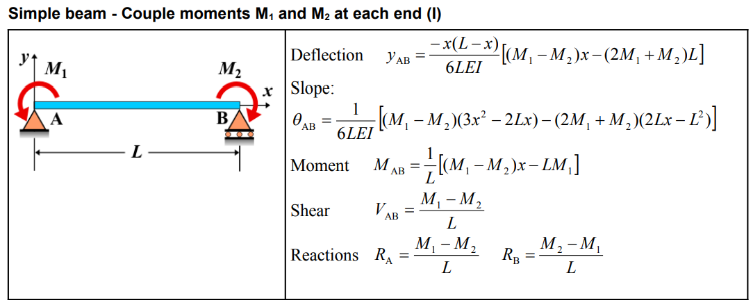
| Deflection (AB) | \( y_{\mathrm{AB}} = \frac{-x(L-x)}{6 L E I}\left[\left(M_1-M_2\right) x-\left(2 M_1+M_2\right) L\right] \) |
| Slope (AB) | \[ \theta_{\mathrm{AB}} = \frac{1}{6 L E I}\left[\left(M_1-M_2\right)\left(3 x^2-2 L x\right)-\left(2 M_1+M_2\right)\left(2 L x-L^2\right)\right] \] |
| Moment (AB) | \( M_{\mathrm{AB}} = \frac{1}{L}\left[\left(M_1-M_2\right) x-L M_1\right] \) |
| Shear (AB) | \( V_{\mathrm{AB}} = \frac{M_1-M_2}{L} \) |
| Reactions | \( R_{\mathrm{A}} = \frac{M_1-M_2}{L} \quad R_{\mathrm{B}} = \frac{M_2-M_1}{L} \) |
Definitions
| Symbol | Physical quantity | Units |
|---|---|---|
| E·I | Flexural rigidity | N·m², Pa·m⁴ |
| y | Deflection or deformation | m |
| θ | Slope, Angle of rotation | - |
| x | Distance from support (origin) | m |
| L | Length of beam (without overhang) | m |
| M | Moment, Bending moment, Couple moment applied | N·m |
| P | Concentrated load, Point load, Concentrated force | N |
| w | Distributed load, Load per unit length | N/m |
| R | Reaction load, reaction force | N |
| V | Shear force, shear | N |