 Home
Home Back
BackSimple beam - Couple moment Mo at left end II Calculator
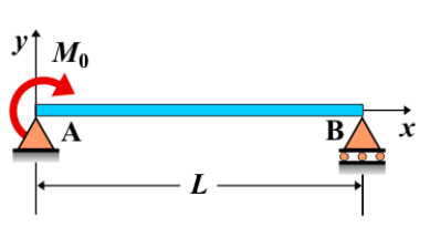
Simple Beam - Couple Moment Mo at Left End II
A simple beam is supported at both ends, with a couple moment \( M_0 \) applied at the left end of the beam. The couple moment induces a rotational effect along the beam, which does not cause a shear force but results in a bending moment throughout the beam. The bending moment diagram shows a constant value of \( M_0 \) along the beam except at the left end, where the moment is applied.
Key Concepts
- Simple Beam: A beam supported at both ends, without any intermediate supports.
- Couple Moment at Left End: A couple moment applied at the left end of the beam, creating a rotational effect, which leads to bending along the beam.
- Shear Force: No shear force is generated by the couple moment, as it does not result in any translational forces on the beam.
- Bending Moment: The bending moment is constant throughout the beam except at the left end, where the couple moment is applied. The magnitude of the moment is \( M_0 \) at every point along the beam.
- Deflection: The deflection caused by the couple moment depends on the moment's magnitude, the beam's length, and the material properties. The deflection will be uniform along the length of the beam.
Behavior of the Simple Beam
- Reaction Forces:
- The reaction forces at the supports are calculated using equilibrium equations. Since the couple moment does not generate shear forces, the reactions at the supports are influenced by the bending moment created by the couple.
- Shear Force Diagram:
- As a couple moment does not create shear force, the shear force diagram remains zero along the length of the beam.
- Bending Moment Diagram:
- The bending moment diagram is constant along the entire length of the beam, with the magnitude equal to \( M_0 \), except at the point where the couple is applied (at the left end).
- Deflection: The deflection caused by the couple moment is calculated using beam deflection formulas, which depend on the magnitude of \( M_0 \), the beam's length, and the material properties. The deflection remains uniform across the beam.
Applications
- Structural Engineering: Couple moments applied at the left end of a simple beam are commonly used to model rotation and bending effects in structural components subjected to torsion or rotational forces.
- Construction: This type of loading is often used in the analysis of beams subjected to torsional loads, such as beams in cantilevered structures or frames with applied rotational forces.
- Mechanical Systems: Couple moments at the left end are found in mechanical systems where rotational forces occur, such as in rotating shafts or other mechanical components subjected to torque.
Formula
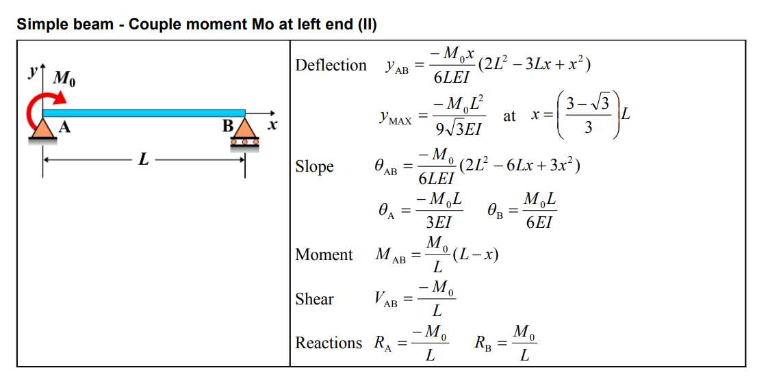
| Deflection (AB) | \( y_{\mathrm{AB}} = \frac{-M_0 x}{6 L E I}\left(2 L^2-3 L x+x^2\right) \) |
| Maximum Deflection | \( y_{\mathrm{MAX}} = \frac{-M_0 L^2}{9 \sqrt{3} E I} \quad \text{at} \quad x = \left(\frac{3-\sqrt{3}}{3}\right) L \) |
| Slope (AB) | \( \theta_{\mathrm{AB}} = \frac{-M_0}{6 L E I}\left(2 L^2-6 L x+3 x^2\right) \) |
| Slope at A | \( \theta_{\mathrm{A}} = \frac{-M_0 L}{3 E I} \) |
| Slope at B | \( \theta_{\mathrm{B}} = \frac{M_0 L}{6 E I} \) |
| Moment (AB) | \( M_{\mathrm{AB}} = \frac{M_0}{L}(L-x) \) |
| Shear (AB) | \( V_{\mathrm{AB}} = \frac{-M_0}{L} \) |
| Reactions | \( R_{\mathrm{A}} = \frac{-M_0}{L} \quad R_{\mathrm{B}} = \frac{M_0}{L} \) |
Definitions
| Symbol | Physical quantity | Units |
|---|---|---|
| E·I | Flexural rigidity | N·m², Pa·m⁴ |
| y | Deflection or deformation | m |
| θ | Slope, Angle of rotation | - |
| x | Distance from support (origin) | m |
| L | Length of beam (without overhang) | m |
| M | Moment, Bending moment, Couple moment applied | N·m |
| P | Concentrated load, Point load, Concentrated force | N |
| w | Distributed load, Load per unit length | N/m |
| R | Reaction load, reaction force | N |
| V | Shear force, shear | N |