 Home
Home Back
BackSimple beam - Couple moment Mo at center Calculator
Results:
Simple Beam - Couple Moment Mo at Center
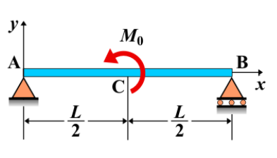
A simple beam is supported at both ends, and a couple moment is applied at the center of the beam. A couple moment \( M_0 \) creates a rotational effect on the beam without causing any shear force. The bending moment diagram shows a constant moment along the length of the beam, except at the center, where the couple moment is applied, causing a shift in the internal bending moment.
Key Concepts
- Simple Beam: A beam supported at both ends, with no intermediate supports.
- Couple Moment at Center: A pair of equal and opposite forces applied at the center of the beam, creating a moment that causes rotational effects without producing shear force.
- Shear Force: No shear force is created by the couple moment, as it does not translate the beam.
- Bending Moment: The bending moment is constant along the length of the beam. However, at the center, where the couple is applied, the bending moment will experience a change due to the applied couple moment \( M_0 \).
- Deflection: The deflection depends on the couple's magnitude, the beam's length, and material properties, with the maximum deflection occurring at the center.
Behavior of the Simple Beam
- Reaction Forces:
- The reaction forces at the supports are calculated using equilibrium equations, with the applied couple moment having no effect on the shear forces but influencing the bending moment at the supports.
- Shear Force Diagram:
- Since a couple moment does not create a shear force, the shear force diagram remains zero throughout the length of the beam.
- Bending Moment Diagram:
- The bending moment diagram remains constant across the entire length of the beam. However, at the center where the couple is applied, the internal bending moment will change by the magnitude of the applied moment \( M_0 \).
- Deflection: The deflection is primarily influenced by the magnitude of the couple moment, the length of the beam, and the material's elasticity. The maximum deflection will occur at the center, where the couple is applied.
Applications
- Structural Engineering: Couple moments applied at the center of beams are used to model rotational effects and bending in structural components, such as beams subjected to twisting forces.
- Construction: This type of loading condition is used in analyzing structural systems where central rotational effects must be considered, such as in cantilevered or supported beams under torsion.
- Mechanical Systems: Couple moments are common in mechanical systems, especially in parts like shafts, beams, or other components that experience rotational forces.
Formula
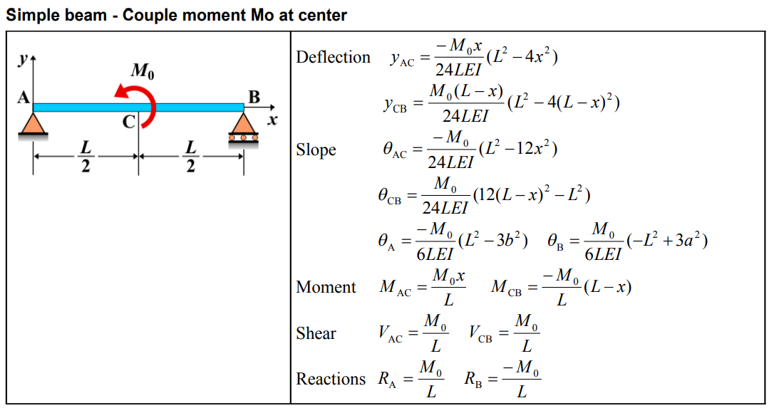
| Deflection (AC) | \( y_{\mathrm{AC}} = \frac{-M_0 x}{24 L E I}\left(L^2-4 x^2\right) \) |
| Deflection (CB) | \( y_{\mathrm{CB}} = \frac{M_0(L-x)}{24 L E I}\left(L^2-4(L-x)^2\right) \) |
| Slope (AC) | \( \theta_{\mathrm{AC}} = \frac{-M_0}{24 L E I}\left(L^2-12 x^2\right) \) |
| Slope (CB) | \( \theta_{\mathrm{CB}} = \frac{M_0}{24 L E I}\left(12(L-x)^2-L^2\right) \) |
| Slope at A | \( \theta_{\mathrm{A}} = \frac{-M_0}{6 L E I}\left(L^2-3 b^2\right) \) |
| Slope at B | \( \theta_{\mathrm{B}} = \frac{M_0}{6 L E I}\left(-L^2+3 a^2\right) \) |
| Moment (AC) | \( M_{\mathrm{AC}} = \frac{M_0 x}{L} \) |
| Moment (CB) | \( M_{\mathrm{CB}} = \frac{-M_0}{L}(L-x) \) |
| Shear (AC) | \( V_{\mathrm{AC}} = \frac{M_0}{L} \) |
| Shear (CB) | \( V_{\mathrm{CB}} = \frac{M_0}{L} \) |
| Reactions | \( R_{\mathrm{A}} = \frac{M_0}{L} \quad R_{\mathrm{B}} = \frac{-M_0}{L} \) |
Definitions
| Symbol | Physical quantity | Units |
|---|---|---|
| E·I | Flexural rigidity | N·m², Pa·m⁴ |
| y | Deflection or deformation | m |
| θ | Slope, Angle of rotation | - |
| x | Distance from support (origin) | m |
| L | Length of beam (without overhang) | m |
| M | Moment, Bending moment, Couple moment applied | N·m |
| P | Concentrated load, Point load, Concentrated force | N |
| w | Distributed load, Load per unit length | N/m |
| R | Reaction load, reaction force | N |
| V | Shear force, shear | N |