 Home
Home Back
BackSimple beam - Concentrated load at center Calculator
Results:
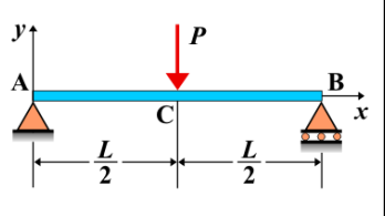
Simple Beam - Concentrated Load at Center
A simple beam is a beam supported at both ends, typically with the ends free to rotate and translate. When a concentrated load is applied exactly at the center of the beam, it creates internal forces and deformations that affect the beam's shear force, bending moment, and deflection. The reaction forces at the supports are equal, and the bending moment is symmetric about the center of the beam.
Key Concepts
- Simple Beam: A beam supported at both ends, with no intermediate supports.
- Concentrated Load at Center: A load applied exactly at the center of the beam, producing symmetric internal forces and deformations.
- Shear Force: The shear force is symmetric along the beam, with maximum values at the supports. The shear force is constant between the supports, and there is a discontinuity at the location of the load application.
- Bending Moment: The bending moment reaches its maximum value at the center of the beam, where the load is applied. The moment decreases linearly toward the supports.
- Deflection: The maximum deflection occurs at the center of the beam, where the concentrated load is applied.
Behavior of the Simple Beam
- Reaction Forces:
- The reactions at the supports are equal and can be determined using equilibrium equations. Each support carries half of the total concentrated load applied at the center.
- Shear Force Diagram:
- The shear force diagram shows a constant value between the supports and a jump at the center where the load is applied. The shear force is positive on one side of the center and negative on the other side.
- Bending Moment Diagram:
- The bending moment diagram is symmetric. The bending moment increases linearly from the supports to the center, where it reaches its maximum value. After the center, the moment decreases linearly toward the opposite support.
- Deflection: The maximum deflection occurs at the center of the beam, where the load is applied. The deflection can be calculated using beam deflection formulas, depending on the magnitude of the load, the length of the beam, and the material properties of the beam.
Applications
- Structural Engineering: Simple beams with concentrated loads at the center are used in many structural applications, such as bridges, roofs, and floors, where loads are applied symmetrically.
- Construction: This loading condition is common in construction, such as when a central column supports a beam or slab.
- Mechanical Systems: In mechanical engineering, this configuration is used in scenarios where a central load is applied to beams or components, such as in testing or load-bearing machinery.
Formula
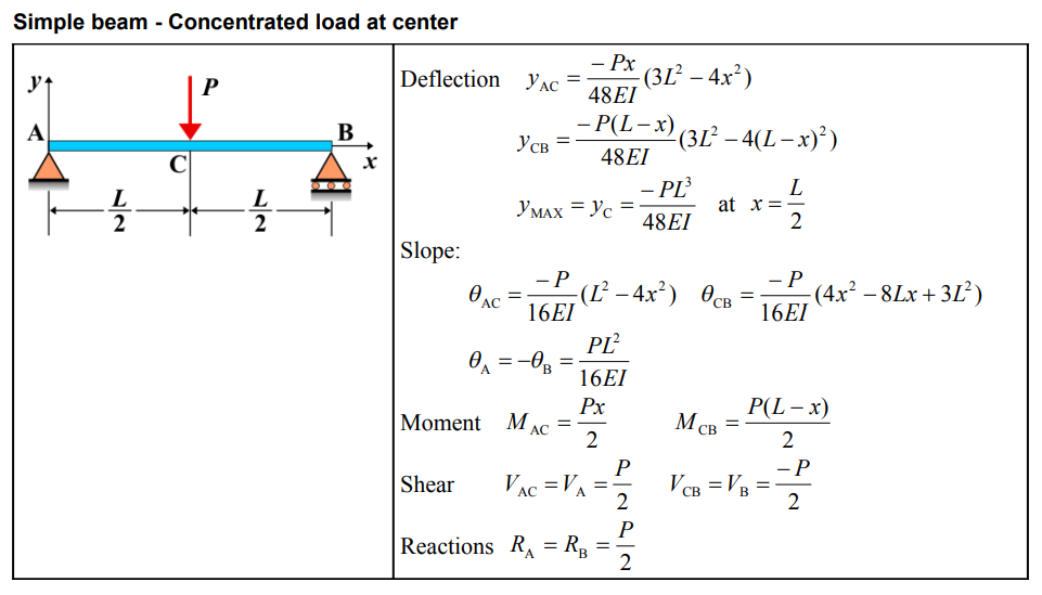
| Deflection (AC) | \( y_{\mathrm{AC}} = \frac{-Px}{48EI}(3L^{2}-4x^{2}) \) |
| Deflection (CB) | \( y_{\mathrm{CB}} = \frac{-P(L-x)}{48EI}(3L^{2}-4(L-x)^{2}) \) |
| Maximum Deflection | \( y_{\mathrm{MAX}} = y_{\mathrm{C}} = \frac{-PL^{3}}{48EI} \quad \mathrm{at} \quad x = \frac{L}{2} \) |
| Slope (AC) | \( \theta_{\mathrm{AC}} = \frac{-P}{16EI}(L^{2}-4x^{2}) \) |
| Slope (CB) | \( \theta_{\mathrm{CB}} = \frac{-P}{16EI}(4x^{2}-8Lx+3L^{2}) \) |
| Slope at A and B | \( \theta_{\mathrm{A}} = -\theta_{\mathrm{B}} = \frac{PL^{2}}{16EI} \) |
| Moment (AC) | \( M_{\mathrm{AC}} = \frac{Px}{2} \) |
| Moment (CB) | \( M_{\mathrm{CB}} = \frac{P(L-x)}{2} \) |
| Shear (AC) | \( V_{\mathrm{AC}} = V_{\mathrm{A}} = \frac{P}{2} \) |
| Shear (CB) | \( V_{\mathrm{CB}} = V_{\mathrm{B}} = \frac{-P}{2} \) |
| Reactions | \( R_{\mathrm{A}} = R_{\mathrm{B}} = \frac{P}{2} \) |
Definitions
| Symbol | Physical quantity | Units |
|---|---|---|
| E·I | Flexural rigidity | N·m², Pa·m⁴ |
| y | Deflection or deformation | m |
| θ | Slope, Angle of rotation | - |
| x | Distance from support (origin) | m |
| L | Length of beam (without overhang) | m |
| M | Moment, Bending moment, Couple moment applied | N·m |
| P | Concentrated load, Point load, Concentrated force | N |
| w | Distributed load, Load per unit length | N/m |
| R | Reaction load, reaction force | N |
| V | Shear force, shear | N |