 Home
Home Back
BackOverhanging beam - Uniformly distributed load Calculator
Results:
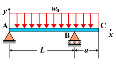
Overhanging Beam - Uniformly Distributed Load
An overhanging beam is a beam supported at two points, with one or both ends extending beyond the supports, creating an overhang. When a uniformly distributed load (UDL) is applied along the length of the overhanging beam, it produces internal forces and deformations that vary along the length of the beam. The load affects the shear force, bending moment, and deflection along the beam, with the overhanging portion experiencing different effects compared to the supported section.
Key Concepts
- Overhanging Beam: A beam with one or both ends extending beyond its supports, leaving part of the beam unsupported.
- Uniformly Distributed Load (UDL): A load that is spread evenly along a portion of the beam. In this case, the UDL is applied over the length of the overhang.
- Shear Force: The shear force in the beam is greatest at the supports and decreases as you move along the beam, with the overhang experiencing a shear force influenced by the UDL. Shear force near the free end will be directly affected by the magnitude of the UDL applied to the overhanging section.
- Bending Moment: The bending moment varies along the beam, reaching a maximum near the fixed support. The moment increases due to the UDL applied to the overhang and decreases as you move away from the overhang.
- Deflection: The deflection is greatest at the free end of the overhang. The magnitude of deflection is influenced by the load, the overhang length, and the material and cross-sectional properties of the beam. The deflection formula depends on the UDL and the length of the overhang.
Behavior of the Overhanging Beam
- Reaction Forces:
- The reactions at the supports can be determined using equilibrium equations. The support closest to the overhang will carry more load, while the other support will bear a reduced load. The reaction forces include vertical forces and a reaction moment at the fixed support.
- Shear Force Diagram:
- The shear force diagram shows a linear variation along the beam. At the free end of the overhang, the shear force will be determined by the magnitude of the UDL applied to the overhanging portion. The shear force will gradually decrease toward the support, where the shear force is greatest.
- Bending Moment Diagram:
- The bending moment diagram increases from the fixed support and reaches a maximum value at a point influenced by the UDL applied to the overhang. The bending moment decreases as you move along the beam towards the free end of the overhang, where the moment is zero.
- Deflection: The maximum deflection occurs at the free end of the overhang and is influenced by the length of the overhang and the magnitude of the UDL. The deflection formula for the free end can be derived using beam theory and is given by: \[ \delta_{\text{max}} = \frac{w L^4}{8 E I} \] where \( w \) is the uniform load intensity, \( L \) is the length of the overhang, \( E \) is the modulus of elasticity, and \( I \) is the moment of inertia of the beam's cross-section.
Applications
- Structural Engineering: Overhanging beams with uniform loads are commonly used in situations where the beam needs to extend beyond the support, such as in bridges, balconies, or roofs with cantilevered sections.
- Construction: This configuration is used in the construction of overhanging parts of buildings or cantilevered sections, where part of the beam must carry a distributed load across its length.
- Mechanical Systems: In mechanical systems, overhanging beams with UDLs are seen in applications where the structure extends from its support, such as conveyor systems, crane arms, or extended frames bearing a uniform load.
Formula
| Category | Formula |
|---|---|
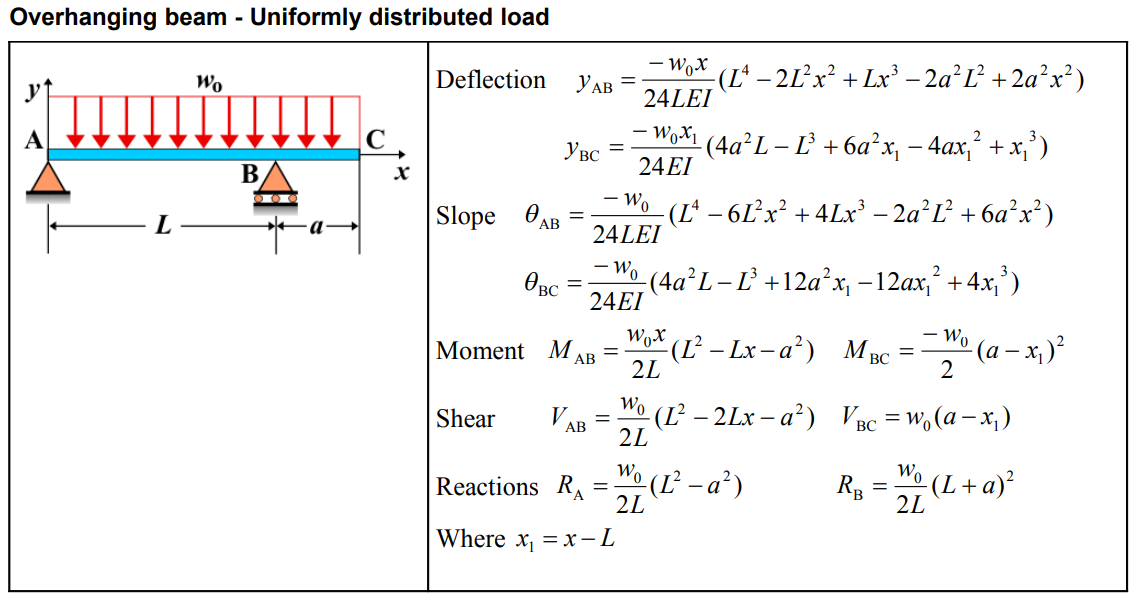
| Deflection \( y_{AB} \) | \[ y_{AB} = \frac{-w_{0}x}{24LEI} \left( L^4 - 2L^2x^2 + Lx^3 - 2a^2L^2 + 2a^2x^2 \right) \] |
| Deflection \( y_{BC} \) | \[ y_{BC} = \frac{-w_{0}x_1}{24EI} \left( 4a^2L - L^3 + 6a^2x_1 - 4ax_1^2 + x_1^3 \right) \] |
| Slope \( \theta_{AB} \) | \[ \theta_{AB} = \frac{-w_{0}}{24LEI} \left( L^4 - 6L^2x^2 + 4Lx^3 - 2a^2L^2 + 6a^2x^2 \right) \] |
| Slope \( \theta_{BC} \) | \[ \theta_{BC} = \frac{-w_{0}}{24EI} \left( 4a^2L - L^3 + 12a^2x_1 - 12ax_1^2 + 4x_1^3 \right) \] |
| Moment \( M_{AB} \) | \[ M_{AB} = \frac{w_{0}x}{2L} \left( L^2 - Lx - a^2 \right) \] |
| Moment \( M_{BC} \) | \[ M_{BC} = \frac{-w_{0}}{2} \left( a - x_1 \right)^2 \] |
| Shear \( V_{AB} \) | \[ V_{AB} = \frac{w_{0}}{2L} \left( L^2 - 2Lx - a^2 \right) \] |
| Shear \( V_{BC} \) | \[ V_{BC} = w_{0} \left( a - x_1 \right) \] |
| Reactions \( R_A \), \( R_B \) | \[ R_A = \frac{w_{0}}{2L} \left( L^2 - a^2 \right), \quad R_B = \frac{w_{0}}{2L} \left( L + a \right)^2 \] |
| Where \( x_1 \) | \[ x_1 = x - L \] |
Definitions
| Symbol | Physical quantity | Units |
|---|---|---|
| E·I | Flexural rigidity | N·m², Pa·m⁴ |
| y | Deflection or deformation | m |
| θ | Slope, Angle of rotation | - |
| x | Distance from support (origin) | m |
| L | Length of beam (without overhang) | m |
| M | Moment, Bending moment, Couple moment applied | N·m |
| P | Concentrated load, Point load, Concentrated force | N |
| w | Distributed load, Load per unit length | N/m |
| R | Reaction load, reaction force | N |
| V | Shear force, shear | N |