 Home
Home Back
BackOverhanging beam - Uniformly distributed load on overhang Calculator
Results:
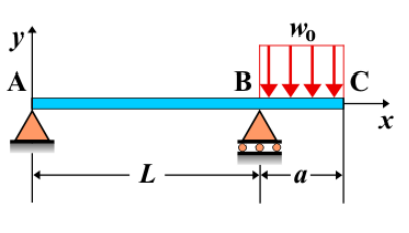
Overhanging Beam - Uniformly Distributed Load on Overhang
An overhanging beam is a beam supported at two points, with one end extending beyond the support, creating an overhang. When a uniformly distributed load (UDL) is applied along the length of the overhang, it generates internal forces and deformations that are influenced by the magnitude and distribution of the load. This loading configuration produces shear forces, bending moments, and deflections that are particularly significant in the overhanging section of the beam.
Key Concepts
- Overhanging Beam: A beam supported at two points, with one end extending beyond the supports, creating an overhang.
- Uniformly Distributed Load (UDL) on Overhang: A load that is evenly spread along the overhanging portion of the beam, producing varying internal forces and deformations along that length.
- Shear Force: The shear force along the beam varies, with the maximum shear force occurring at the fixed support and reducing as the load is applied along the overhang. At the free end of the overhang, the shear force is zero.
- Bending Moment: The bending moment is greatest at the fixed support, increasing as you move along the beam toward the overhang. The moment reduces along the overhang but remains influenced by the distributed load.
- Deflection: The deflection is maximum at the free end of the overhang. The magnitude of deflection depends on the length of the overhang, the applied load, and the beam's material and cross-sectional properties.
Behavior of the Overhanging Beam
- Reaction Forces:
- The reactions at the supports can be determined using equilibrium equations. The fixed support closest to the overhang will bear the majority of the load, while the other support will carry a reduced portion of the load. Reaction forces include vertical forces and a reaction moment at the fixed support.
- Shear Force Diagram:
- The shear force diagram will show a linear variation along the beam. At the free end of the overhang, the shear force is zero. The shear force is highest at the fixed support, influenced by the magnitude of the UDL applied to the overhanging section.
- Bending Moment Diagram:
- The bending moment diagram shows a maximum moment near the fixed support and decreases towards the free end of the overhang. The moment varies linearly due to the uniformly distributed load applied along the overhang.
- Deflection: The maximum deflection occurs at the free end of the overhang. The deflection formula for this configuration is derived using beam theory and is given by: \[ \delta_{\text{max}} = \frac{w L^4}{8 E I} \] where \( w \) is the uniform load intensity, \( L \) is the length of the overhang, \( E \) is the modulus of elasticity, and \( I \) is the moment of inertia of the beam's cross-section.
Applications
- Structural Engineering: Overhanging beams with uniformly distributed loads are commonly used in structures such as bridges, balconies, and roofs with cantilevered sections where part of the structure extends beyond its supports.
- Construction: This type of loading is typical in building construction, particularly for cantilevered sections that extend out beyond the main structure.
- Mechanical Systems: Overhanging beams with UDLs are seen in mechanical systems where parts of the structure extend from their supports, such as crane arms or conveyor systems.
Formula
| Category | Formula |
|---|---|
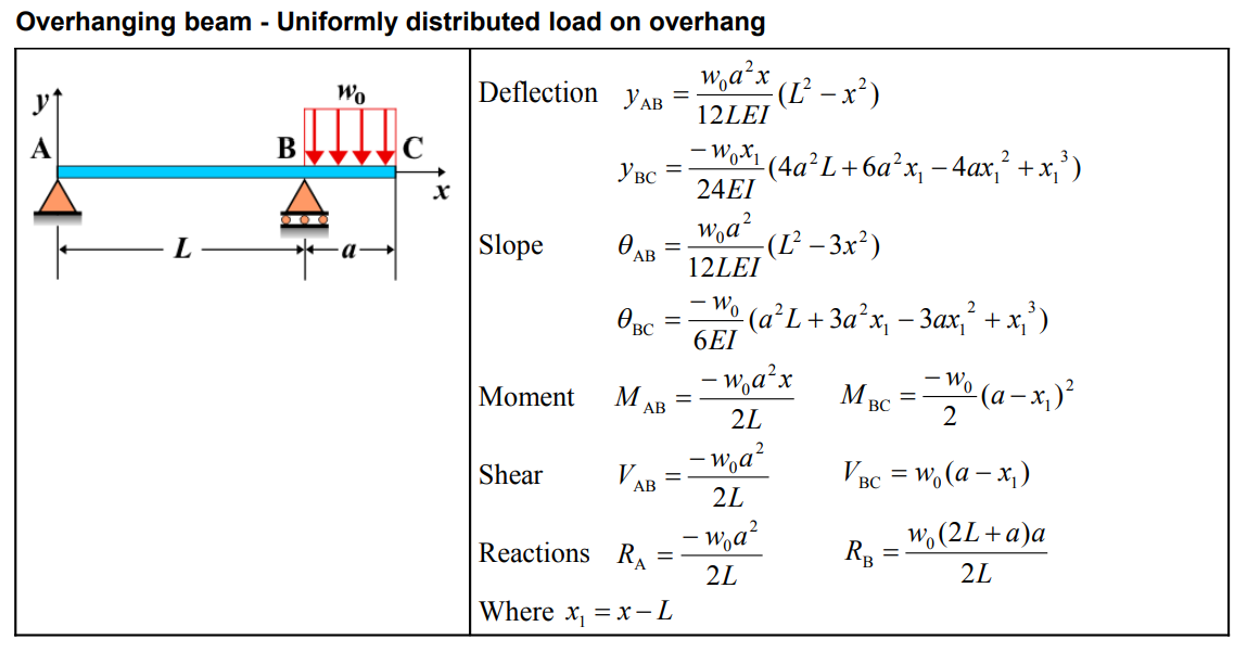
| Deflection \( y_{AB} \) | \[ y_{AB} = \frac{w_{0}a^2x}{12LEI} \left( L^2 - x^2 \right) \] |
| Deflection \( y_{BC} \) | \[ y_{BC} = \frac{-w_{0}x_1}{24EI} \left( 4a^2L + 6a^2x_1 - 4ax_1^2 + x_1^3 \right) \] |
| Slope \( \theta_{AB} \) | \[ \theta_{AB} = \frac{w_{0}a^2}{12LEI} \left( L^2 - 3x^2 \right) \] |
| Slope \( \theta_{BC} \) | \[ \theta_{BC} = \frac{-w_{0}}{6EI} \left( a^2L + 3a^2x_1 - 3ax_1^2 + x_1^3 \right) \] |
| Moment \( M_{AB} \) | \[ M_{AB} = \frac{-w_{0}a^2x}{2L} \] |
| Moment \( M_{BC} \) | \[ M_{BC} = \frac{-w_{0}}{2} \left( a - x_1 \right)^2 \] |
| Shear \( V_{AB} \) | \[ V_{AB} = \frac{-w_{0}a^2}{2L} \] |
| Shear \( V_{BC} \) | \[ V_{BC} = w_{0} \left( a - x_1 \right) \] |
| Reactions \( R_A \), \( R_B \) | \[ R_A = \frac{-w_{0}a^2}{2I}, \quad R_B = \frac{w_{0}(2L + a)a}{2L} \] |
| Where \( x_1 \) | \[ x_1 = x - L \] |
Definitions
| Symbol | Physical quantity | Units |
|---|---|---|
| E·I | Flexural rigidity | N·m², Pa·m⁴ |
| y | Deflection or deformation | m |
| θ | Slope, Angle of rotation | - |
| x | Distance from support (origin) | m |
| L | Length of beam (without overhang) | m |
| M | Moment, Bending moment, Couple moment applied | N·m |
| P | Concentrated load, Point load, Concentrated force | N |
| w | Distributed load, Load per unit length | N/m |
| R | Reaction load, reaction force | N |
| V | Shear force, shear | N |