 Home
Home Back
BackOverhanging beam - Concentrated load at any point between supports Calculator
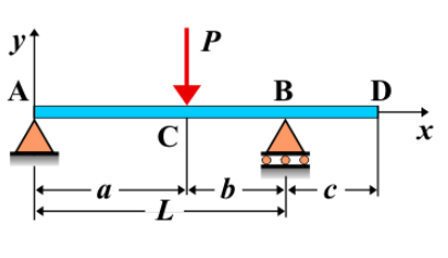
Overhanging Beam - Concentrated Load at Any Point Between Supports
An **overhanging beam** is a beam that extends beyond its supports, meaning that part of the beam is unsupported at one or both ends. When a **concentrated load** is applied at any point between the supports, it causes internal forces, such as shear force and bending moment, to be distributed along the beam. This type of loading condition results in a unique distribution of internal stresses, which can lead to specific deflections and moments, particularly at the overhanging portion of the beam.
Key Concepts
- Overhanging Beam: A beam that is supported at two points, with one or both ends extending beyond the supports. The overhanging portion of the beam does not have direct support.
- Concentrated Load: A load that is applied at a single point, as opposed to a distributed load. This load can be applied anywhere between the supports of the beam.
- Shear Force: The shear force varies along the length of the beam. It is influenced by the location and magnitude of the applied concentrated load. The shear force diagram will have jumps at the locations where the load is applied, and the shear force will be greatest near the supports.
- Bending Moment: The bending moment varies along the beam, with the maximum bending moment occurring at the location of the applied load. The moment at the overhanging portion is particularly important as it is influenced by the load and the moment reactions from the supports.
- Deflection: The deflection is greatest at the free end of the overhang and decreases as you move toward the supports. The deflection is caused by the bending of the beam under the concentrated load.
Behavior of the Overhanging Beam
- Reaction Forces:
- The reaction forces at the supports can be calculated by applying the equilibrium equations. The support reactions include vertical forces at the supports, and possibly a moment reaction at the fixed support if applicable.
- The reactions are influenced by the magnitude and location of the concentrated load, as well as the span of the overhang.
- Shear Force Diagram:
- The shear force diagram will show jumps in shear force at the point where the concentrated load is applied. The diagram will have a discontinuity at the load's location and will vary linearly between the supports.
- The shear force will be highest at the supports and decrease toward the free end of the overhang.
- Bending Moment Diagram:
- The bending moment diagram will have a peak at the location of the applied load. The moment will vary along the beam, with the maximum bending moment typically occurring at or near the point of load application.
- In the overhanging section, the bending moment will be influenced by both the applied load and the support reactions, and it may exhibit a downward curve in the overhanging portion.
- Deflection: The deflection is greatest at the free end of the overhang, where the beam is not supported. The deflection will decrease towards the supports. The deflection is influenced by the beam's material properties, its length, and the location of the applied load. The formula for deflection at any point along the beam can be derived using beam theory, and the maximum deflection occurs at the free end.
Applications
- Structural Engineering: Overhanging beams are commonly used in construction for situations where space constraints or other factors require part of the beam to extend beyond the support structure, such as balconies, cantilevers, or bridges.
- Construction: Overhanging beams are often used in the construction of buildings, where they can support loads overhanging structures such as roof eaves or overhangs of floors.
- Mechanical Systems: This type of loading can also be found in mechanical systems where overhanging parts are subject to concentrated forces, such as in crane booms or conveyor systems.
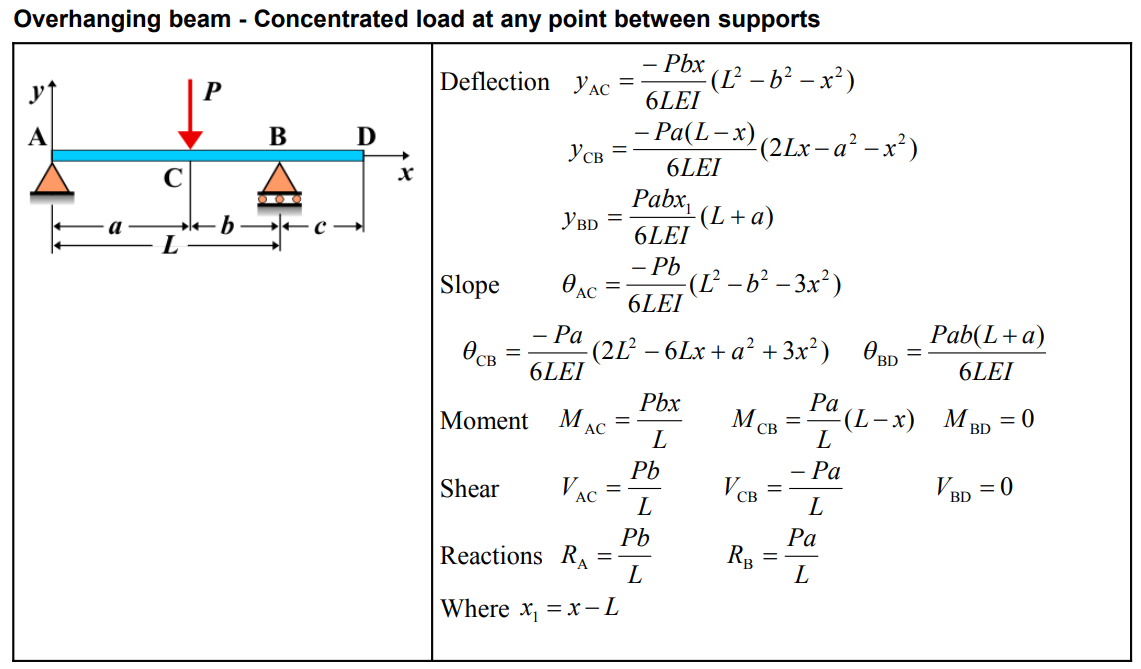
Formula
| Category | Formula |
|---|---|
| Deflection \( y_{AC} \) | \[ y_{AC} = \frac{-Pbx}{6LEI} \left( L^2 - b^2 - x^2 \right) \] |
| Deflection \( y_{CB} \) | \[ y_{CB} = \frac{-Pa(L-x)}{6LEI} \left( 2Lx - a^2 - x^2 \right) \] |
| Deflection \( y_{BD} \) | \[ y_{BD} = \frac{Pabx_1}{6LEI} \left( L + a \right) \] |
| Slope \( \theta_{AC} \) | \[ \theta_{AC} = \frac{-Pb}{6LEI} \left( L^2 - b^2 - 3x^2 \right) \] |
| Slope \( \theta_{CB} \) | \[ \theta_{CB} = \frac{-Pa}{6LEI} \left( 2L^2 - 6Lx + a^2 + 3x^2 \right) \] |
| Slope \( \theta_{BD} \) | \[ \theta_{BD} = \frac{Pab(L+a)}{6LEI} \] |
| Moment \( M_{AC} \) | \[ M_{AC} = \frac{Pbx}{L} \] |
| Moment \( M_{CB} \) | \[ M_{CB} = \frac{Pa}{L} (L - x) \] |
| Moment \( M_{BD} \) | \[ M_{BD} = 0 \] |
| Shear \( V_{AC} \) | \[ V_{AC} = \frac{Pb}{L} \] |
| Shear \( V_{CB} \) | \[ V_{CB} = \frac{-Pa}{L} \] |
| Shear \( V_{BD} \) | \[ V_{BD} = 0 \] |
| Reactions \( R_A \), \( R_B \) | \[ R_A = \frac{Pb}{L}, \quad R_B = \frac{Pa}{L} \] |
| Where \( x_1 \) | \[ x_1 = x - L \] |
Definitions
| Symbol | Physical quantity | Units |
|---|---|---|
| E·I | Flexural rigidity | N·m², Pa·m⁴ |
| y | Deflection or deformation | m |
| θ | Slope, Angle of rotation | - |
| x | Distance from support (origin) | m |
| L | Length of beam (without overhang) | m |
| M | Moment, Bending moment, Couple moment applied | N·m |
| P | Concentrated load, Point load, Concentrated force | N |
| w | Distributed load, Load per unit length | N/m |
| R | Reaction load, reaction force | N |
| V | Shear force, shear | N |