 Home
Home Back
BackFixed-pinned beam - Uniformly distributed load Calculator
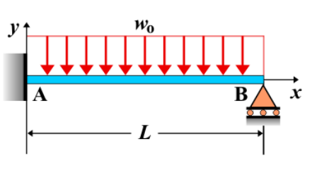
Fixed-Pinned Beam - Uniformly Distributed Load
A **fixed-pinned beam** is a beam that is fixed at one end and pinned at the other. When a **uniformly distributed load** is applied along the entire length of the beam, it creates a specific internal force distribution that influences shear forces, bending moments, and deflection along the beam. The load is applied uniformly across the entire span of the beam, which results in a symmetrical response in the beam's structural behavior.
Key Concepts
- Uniformly Distributed Load: A load that is evenly spread over the entire length of the beam, typically expressed as a force per unit length (e.g., N/m).
- Fixed-Pinned Beam: A beam that is fixed at one end (resisting both translation and rotation) and pinned at the other end (allowing rotation but preventing translation).
- Shear Force: The shear force along the beam varies due to the applied uniform load. The shear force will be highest near the fixed support and gradually decreases towards the pinned support.
- Bending Moment: The bending moment is influenced by the uniformly distributed load, increasing along the beam's length, with the maximum moment occurring at the fixed end.
- Deflection: The deflection of the beam increases along the length, with the maximum deflection occurring at the free end. The deflection follows a smooth curve due to the constant load distribution.
Behavior of the Fixed-Pinned Beam
- Reaction Forces:
- The reaction forces at the fixed and pinned supports are determined using equilibrium equations. The fixed support resists both vertical forces and a moment, while the pinned support only resists vertical forces.
- The total vertical reaction force at the fixed support is equal to the total applied load, and the moment reaction at the fixed support is influenced by the location of the uniform load.
- Shear Force Diagram:
- The shear force at the fixed support is at its maximum and gradually decreases as you move towards the pinned support. The shear force diagram is a straight line that slopes downward, with the slope equal to the magnitude of the applied uniform load.
- The shear force becomes zero at the pinned end, indicating that there is no shear force beyond the point where the load is applied.
- Bending Moment Diagram:
- The bending moment is maximum at the fixed support and decreases linearly towards the pinned support. The moment diagram forms a curve, typically parabolic, with the highest value at the fixed end.
- The bending moment at any point along the beam can be calculated by integrating the shear force, and the maximum bending moment occurs at the fixed end of the beam.
- Deflection: The deflection follows a smooth curve, with the maximum deflection occurring at the free end. The deflection is influenced by the beam's length, material properties, and the uniform load. The formula for maximum deflection is: \[ \delta_{\text{max}} = \frac{5 w L^4}{384 E I} \] where \( w \) is the magnitude of the uniform load, \( L \) is the length of the beam, \( E \) is the modulus of elasticity, and \( I \) is the moment of inertia of the beam’s cross-section.
Applications
- Structural Engineering: This type of loading condition is common in beams supporting structural loads, such as floors, roofs, and bridges, where the load is uniformly distributed along the beam’s span.
- Construction: Uniformly distributed loads are often encountered in building design, where loads like the weight of walls, floors, and roofs are spread out evenly across the length of the supporting beams.
- Mechanical Systems: Beams subjected to uniform loads are also common in mechanical systems where components are uniformly loaded across their length, such as machine frames or supports for moving parts.
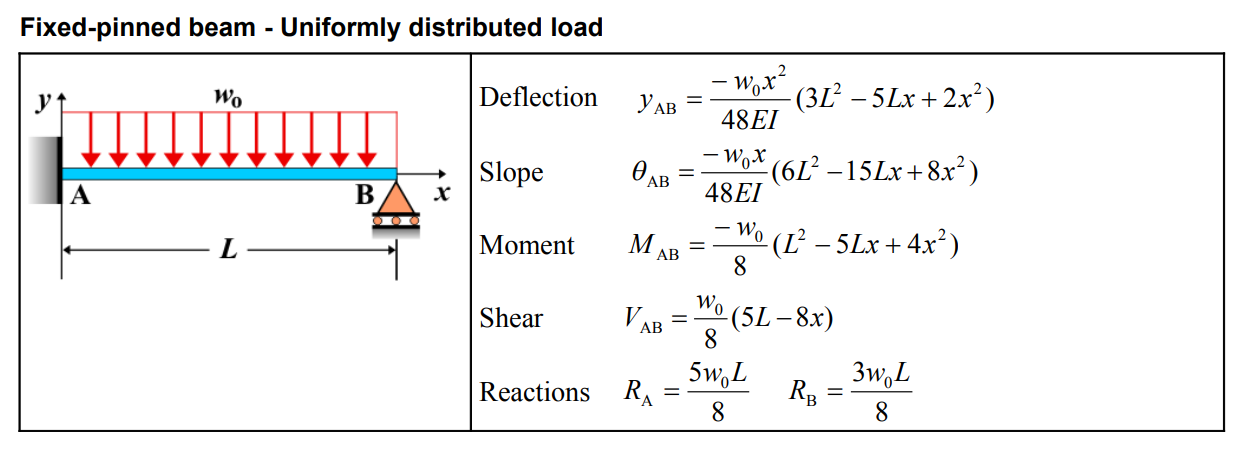
Formula
| Category | Formula |
|---|---|
| Deflection \( y_{AB} \) | \[ y_{AB} = \frac{-w_0x^2}{48EI} \left( 3L^2 - 5Lx + 2x^2 \right) \] |
| Slope \( \theta_{AB} \) | \[ \theta_{AB} = \frac{-w_0x}{48EI} \left( 6L^2 - 15Lx + 8x^2 \right) \] |
| Moment \( M_{AB} \) | \[ M_{AB} = \frac{-w_0}{8} \left( L^2 - 5Lx + 4x^2 \right) \] |
| Shear \( V_{AB} \) | \[ V_{AB} = \frac{w_0}{8} \left( 5L - 8x \right) \] |
| Reactions \( R_A \), \( R_B \) | \[ R_A = \frac{5w_0L}{8}, \quad R_B = \frac{3w_0L}{8} \] |
Definitions
| Symbol | Physical quantity | Units |
|---|---|---|
| E·I | Flexural rigidity | N·m², Pa·m⁴ |
| y | Deflection or deformation | m |
| θ | Slope, Angle of rotation | - |
| x | Distance from support (origin) | m |
| L | Length of beam (without overhang) | m |
| M | Moment, Bending moment, Couple moment applied | N·m |
| P | Concentrated load, Point load, Concentrated force | N |
| w | Distributed load, Load per unit length | N/m |
| R | Reaction load, reaction force | N |
| V | Shear force, shear | N |