 Home
Home Back
BackFixed-pinned beam - Uniform load partially distributed Calculator
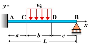
Fixed-Pinned Beam - Uniform Load Partially Distributed
A **fixed-pinned beam** is a beam that is fixed at one end and pinned at the other. When a **uniform load** is applied to only a portion of the beam, the load distribution is uniform over that section of the beam. This type of load produces specific internal forces, including shear force, bending moment, and deflection, which vary along the beam's length. The load affects the beam's behavior differently than a uniform load applied over the entire span.
Key Concepts
- Uniform Load: A load that is evenly distributed over a section of the beam. In this case, the load is applied only over a portion of the beam, not the entire span.
- Fixed-Pinned Beam: A beam that is fixed at one end (prevents both translation and rotation) and pinned at the other end (allows rotation but prevents translation).
- Shear Force: The shear force along the beam will vary due to the uniform load applied to part of the beam. The shear force will be highest at the fixed support and decrease as you move away from the fixed end.
- Bending Moment: The bending moment will increase along the length of the beam. The maximum bending moment typically occurs near the fixed end, and its distribution is influenced by the extent of the uniform load.
- Deflection: The deflection of the beam is greatest near the location where the uniform load is applied. The deflection follows a smooth curve due to the nature of the load distribution.
Behavior of the Fixed-Pinned Beam
- Reaction Forces:
- The reaction forces at the fixed and pinned supports can be determined using equilibrium equations. The fixed support has both vertical and moment reactions, while the pinned support has only a vertical reaction.
- The reaction at the fixed end depends on the magnitude and position of the uniformly distributed load. The pinned support reaction is only vertical, but it will be influenced by the load distribution.
- Shear Force Diagram:
- The shear force will be influenced by the applied uniform load, starting at a maximum near the fixed end and decreasing as you move towards the pinned support.
- The shear force diagram will have a linear slope along the length of the beam where the uniform load is applied, and it will decrease as the distance from the fixed end increases.
- Bending Moment Diagram:
- The bending moment increases as you move from the pinned end towards the fixed end. It reaches a maximum near the fixed support, depending on the magnitude and location of the applied load.
- The bending moment distribution is influenced by the uniform load, and the moment diagram will have a parabolic shape as it increases and then decreases along the length of the beam.
- Deflection: The deflection follows a smooth curve, with the maximum deflection occurring near the region where the uniform load is applied. The deflection is greatest at the free end of the beam. The formula for maximum deflection is: \[ \delta_{\text{max}} = \frac{w L^4}{8 E I} \] where \( w \) is the magnitude of the uniform load, \( L \) is the length of the beam, \( E \) is the modulus of elasticity, and \( I \) is the moment of inertia of the beam’s cross-section.
Applications
- Structural Engineering: Common in beams that support structural elements like floors, walls, or roofs with partial loading conditions.
- Construction: Often encountered in building design where parts of beams are subjected to varying loads across their length.
- Mechanical Systems: Found in mechanical structures that are subjected to partial loading, such as frames or supports that bear loads in certain areas.
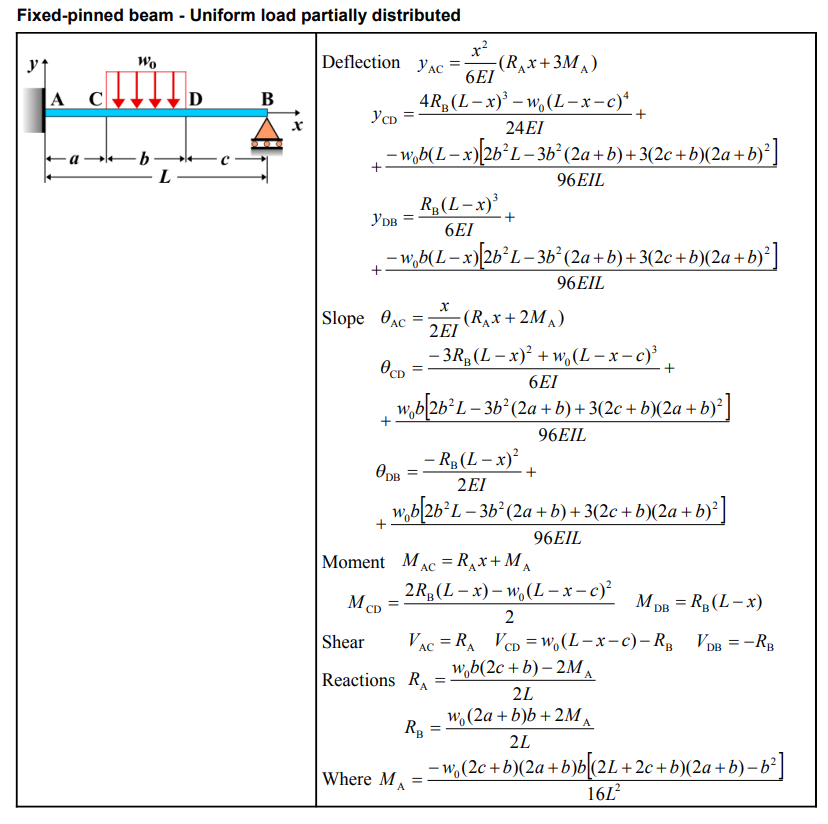
Formula
| Property | Formula |
|---|---|
| Deflection (\(y_{AC}\)) | \(y_{AC} = \frac{Px^2}{12EI L^2} [(3a^2 - 3aL - 2L^2)(L-x) + 2L(3a^2 - 3aL + L^2)]\) |
| Deflection (\(y_{CD}\)) | \(y_{CD} = \frac{-Pa(3(L-a)(L-x)^3 - 6L^2(L-x)^2)}{12EI L^2 a^2} + \frac{-Pa[3L^2(L+a)(L-x) - 2L^2 a]}{12EI L^2}\) |
| Deflection (\(y_{DB}\)) | \(y_{DB} = \frac{-P(L-x)}{12EI L^2} [(3aL - 3a^2 - 2L^2)(L-x)^2 + 3aL^2(L-a)]\) |
| Slope (\(\theta_{AC}\)) | \(\theta_{AC} = \frac{Px}{12EI L^2} [(3a^2 - 3aL - 2L^2)(2L - 3x) + 4L(3a^2 - 3aL + L^2)]\) |
| Slope (\(\theta_{CD}\)) | \(\theta_{CD} = \frac{-Pa}{4EI L^2} [-3(L-a)(L-x)^2 + 4L^2(L-x) - L^2(L+a)]\) |
| Slope (\(\theta_{DB}\)) | \(\theta_{DB} = \frac{P}{4EI L^2} [(3aL - 3a^2 - 2L^2)(L-x)^2 + aL^2(L-a)]\) |
| Moment (\(M_{AC}\)) | \(M_{AC} = \frac{P}{2L^2} [3a^2 L - 3aL^2 + x(2L^2 + 3aL - 3a^2)]\) |
| Moment (\(M_{CD}\)) | \(M_{CD} = \frac{-Pa}{2L^2} [3(L-a)(L-x) - 2L^2]\) |
| Moment (\(M_{DB}\)) | \(M_{DB} = \frac{-P(L-x)}{2L^2} [3aL - 3a^2 - 2L^2]\) |
| Shear (\(V_{AC}\)) | \(V_{AC} = \frac{P}{2L^2} (2L^2 + 3aL - 3a^2)\) |
| Shear (\(V_{CD}\)) | \(V_{CD} = \frac{3Pa(L-a)}{2L^2}\) |
| Shear (\(V_{DB}\)) | \(V_{DB} = \frac{P}{2L^2} (3aL - 3a^2 - 2L^2)\) |
| Reaction (\(R_A\)) | \(R_A = \frac{P}{2L^2} (2L^2 + 3aL - 3a^2)\) |
| Reaction (\(R_B\)) | \(R_B = \frac{P}{2L^2} (3a^2 + 2L^2 - 3aL)\) |
| Deflection (\(y_{AC}\)) - New | \(y_{AC} = \frac{x^2}{6EI} (R_A x + 3M_A)\) |
| Deflection (\(y_{CD}\)) - New | \(y_{CD} = \frac{4R_B(L-x)^3 - w_0(L-x-c)^4}{24EI} + \frac{-w_0 b(L-x)[2b^2 L - 3b^2(2a+t)]}{96EI L}\) |
| Deflection (\(y_{DB}\)) - New | \(y_{DB} = \frac{R_B(L-x)^3}{6EI} + \frac{-w_0 b(L-x)[2b^2 L - 3b^2(2a+b) + 3(2c+b)(2a+b)^2]}{96EI L}\) |
| Slope (\(\theta_{AC}\)) - New | \(\theta_{AC} = \frac{x}{2EI} (R_A x + 2M_A)\) |
| Slope (\(\theta_{CD}\)) - New | \(\theta_{CD} = \frac{-3R_B(L-x)^2 + w_0(L-x-c)^3}{6EI} + \frac{w_0 b[2b^2 L - 3b^2(2a+b) + 3(2c+b)(2a+b)^2]}{96EI L}\) |
| Moment (\(M_{AC}\)) - New | \(M_{AC} = \frac{w_0 b|2b^2 L - 3b^2(2a+b)}{nt} + R x + M_A\) |
| Shear (\(V_{AC}\)) - New | \(V_{AC} = R_A\) |
| Shear (\(V_{CD}\)) - New | \(V_{CD} = w_0 (L-x-c) - R_B\) |
| Shear (\(V_{DB}\)) - New | \(V_{DB} = -R_B\) |
| Reaction (\(R_A\)) - New | \(R_A = \frac{w_0 b(2c+b) - 2M_A}{2L}\) |
| Reaction (\(R_B\)) - New | \(R_B = \frac{w_0(2a+b)b + 2M_A}{2L}\) |
Definitions
| Symbol | Physical quantity | Units |
|---|---|---|
| E·I | Flexural rigidity | N·m², Pa·m⁴ |
| y | Deflection or deformation | m |
| θ | Slope, Angle of rotation | - |
| x | Distance from support (origin) | m |
| L | Length of beam (without overhang) | m |
| M | Moment, Bending moment, Couple moment applied | N·m |
| P | Concentrated load, Point load, Concentrated force | N |
| w | Distributed load, Load per unit length | N/m |
| R | Reaction load, reaction force | N |
| V | Shear force, shear | N |