 Home
Home Back
BackFixed-pinned beam - Uniform load partially distributed at supported end Calculator
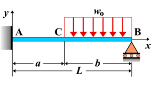
Fixed-Pinned Beam - Uniform Load Partially Distributed at Supported End
A fixed-pinned beam is a beam that is fixed at one end and pinned at the other. When a uniform load is partially distributed near the supported (pinned) end, it creates a specific internal force distribution that results in shear forces, bending moments, and deflections along the beam. The load is applied only over a portion of the beam near the pinned end, and the remaining section of the beam either remains unloaded or is subject to different conditions. This type of loading affects the beam's behavior differently from a uniformly distributed load over the entire span.
Key Concepts
- Uniform Load: A load that is evenly distributed over a section of the beam. In this case, the load is applied only over a portion of the beam near the pinned support.
- Fixed-Pinned Beam: A beam that is fixed at one end (unable to translate or rotate) and pinned at the other end (allowing rotation but preventing translation).
- Shear Force: The shear force varies along the beam due to the uniform load applied at the supported end. The shear force will be highest near the fixed support and gradually decreases as the load is distributed over the span.
- Bending Moment: The bending moment increases along the beam, with the maximum moment occurring at the fixed end. The bending moment is influenced by the magnitude and extent of the uniformly distributed load at the pinned end.
- Deflection: The deflection of the beam is greatest near the pinned support, where the load is applied. The deflection is smooth and follows a curve as the load is distributed along the length of the beam.
Behavior of the Fixed-Pinned Beam
- Reaction Forces:
- The reaction forces at the fixed and pinned supports can be calculated by solving the equilibrium equations. The fixed end will have both vertical and moment reactions, while the pinned support will only have a vertical reaction force.
- The reaction at the fixed support is influenced by the uniform load applied near the pinned end and depends on the length of the loaded portion of the beam.
- Shear Force Diagram:
- The shear force is influenced by the uniform load distribution. The shear force will be positive near the fixed end and decrease linearly as the beam extends towards the pinned end.
- At the point where the uniform load ends, the shear force will drop to zero, indicating the end of the load application.
- Bending Moment Diagram:
- The bending moment will be highest at the fixed end due to the applied uniform load.
- The moment diagram will have a parabolic shape, with the moment gradually decreasing towards the location where the load distribution ends.
- Deflection: The deflection follows a smooth curve with the maximum deflection occurring near the location where the uniform load ends. The deflection is calculated based on the beam's properties and the load distribution. The formula for maximum deflection is: \[ \delta_{\text{max}} = \frac{w L^4}{8 E I} \] where \( w \) is the uniform load per unit length, \( L \) is the length of the beam, \( E \) is the modulus of elasticity, and \( I \) is the moment of inertia of the beam's cross-section.
Applications
- Structural Engineering: This type of loading condition is often encountered in beams that support structural elements, such as floors, walls, or other loads near a pinned support.
- Construction: Beams with loads partially distributed near the supported end are common in building construction, where certain parts of the beam experience heavier loads due to nearby structural elements.
- Mechanical Systems: This loading condition is seen in mechanical systems where parts of a structure or beam experience localized loads at one end, such as machine supports or frames subjected to uneven loading.
Formula
| Category | Formula |
|---|---|
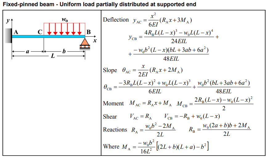
| Deflection \( y_{AC} \) | \[ y_{AC} = \frac{x^2}{6EI} \left( R_A x + 3M_A \right) \] |
| Deflection \( y_{CB} \) | \[ y_{CB} = \frac{4R_B L(L-x)^3 - w_0L(L-x)^4}{24EI L} + \frac{-w_0b^2(L-x)\left(bL + 3ab + 6a^2\right)}{48EI L} \] |
| Slope \( \theta_{AC} \) | \[ \theta_{AC} = \frac{x}{2EI} \left( R_A x + 2M_A \right) \] |
| Slope \( \theta_{CB} \) | \[ \theta_{CB} = \frac{-3R_B L(L-x)^2 + w_0L(L-x)^3}{6EI L} + \frac{w_0b^2 \left(bL + 3ab + 6a^2\right)}{48EI L} \] |
| Moment \( M_{AC} \) | \[ M_{AC} = R_A x + M_A \] |
| Moment \( M_{CB} \) | \[ M_{CB} = \frac{2R_B(L-x) - w_0(L-x)^2}{2} \] |
| Shear \( V_{AC} \) | \[ V_{AC} = R_A \] |
| Shear \( V_{CB} \) | \[ V_{CB} = -R_B + w_0(L-x) \] |
| Reaction \( R_A \) | \[ R_A = \frac{w_0b^2 - 2M_A}{2L} \] |
| Reaction \( R_B \) | \[ R_B = \frac{w_0\left(2a + b\right)b + 2M_A}{2L} \] |
| Where \( M_A \) | \[ M_A = \frac{-w_0b^2}{16L^2} \left[2L + b)(L+a) - b^2\right] \] |
Definitions
| Symbol | Physical quantity | Units |
|---|---|---|
| E·I | Flexural rigidity | N·m², Pa·m⁴ |
| y | Deflection or deformation | m |
| θ | Slope, Angle of rotation | - |
| x | Distance from support (origin) | m |
| L | Length of beam (without overhang) | m |
| M | Moment, Bending moment, Couple moment applied | N·m |
| P | Concentrated load, Point load, Concentrated force | N |
| w | Distributed load, Load per unit length | N/m |
| R | Reaction load, reaction force | N |
| V | Shear force, shear | N |