 Home
Home Back
BackFixed-pinned beam - Uniform load partially distributed at fixed end Calculator
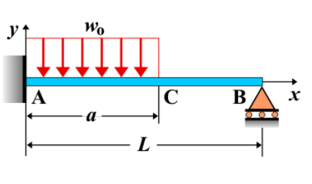
Fixed-Pinned Beam - Uniform Load Partially Distributed at the Fixed End
A **fixed-pinned beam** is a beam that is fixed at one end and pinned at the other. When a **uniform load** is partially distributed at the fixed end, the load distribution is uniform over a portion of the beam near the fixed support, and the remaining part of the beam is either unloaded or subjected to different conditions. This type of loading creates specific internal force distributions, including shear force, bending moment, and deflection, which vary along the length of the beam.
Key Concepts
- Uniform Load: A load that is distributed evenly along a section of the beam. In this case, the load is uniform only over the portion near the fixed end.
- Fixed-Pinned Beam: A beam fixed at one end, preventing both translation and rotation, and pinned at the other end, which allows rotation but prevents translation at the pinned support.
- Shear Force: The shear force distribution is affected by the uniform load. It will vary linearly along the length of the beam, with the maximum shear at the fixed end and decreasing towards the pinned support.
- Bending Moment: The bending moment increases as the uniform load is applied, with the maximum bending moment occurring at the fixed end. The bending moment distribution is influenced by both the length and magnitude of the uniform load section.
- Deflection: The deflection varies along the length of the beam, with the maximum deflection occurring at the location of the applied load, typically towards the free end.
Behavior of the Fixed-Pinned Beam
- Reaction Forces:
- The reaction forces at the fixed and pinned supports can be calculated by solving the equilibrium equations for the beam. The uniform load applied at the fixed end produces a reaction at both supports.
- The reaction at the fixed end will include both a vertical force and a moment. The reaction at the pinned end will only include a vertical force.
- Shear Force Diagram:
- The shear force diagram will be influenced by the applied uniform load. The shear force will increase linearly along the beam, reaching its maximum value at the fixed support.
- As the beam moves away from the fixed end, the shear force will decrease gradually, eventually becoming zero at the location where the load distribution ends.
- Bending Moment Diagram:
- The bending moment will be highest at the fixed end of the beam due to the uniformly distributed load.
- The moment increases quadratically as you move along the beam from the pinned end towards the fixed end, with the maximum bending moment at the fixed support.
- The moment diagram shows a curve, with the moment increasing as the uniform load is applied.
- Deflection: The deflection of the beam is influenced by the uniform load distribution. The deflection is greatest at the point of load application and follows a curved path. The deflection at any point along the beam can be calculated using beam deflection formulas, considering the uniform load and the beam's properties: \[ \delta_{\text{max}} = \frac{w L^4}{8 E I} \] where \( w \) is the magnitude of the uniform load per unit length, \( L \) is the length of the beam, \( E \) is the modulus of elasticity, and \( I \) is the moment of inertia of the beam’s cross-section.
Applications
- Structural Engineering: Common in buildings, bridges, and other structures where parts of the beam are subjected to uniform loads, such as floors with uneven load distribution.
- Construction: This loading condition occurs in beams supporting elements like walls, roofs, or machinery where the load is distributed unevenly across the span.
- Mechanical Systems: In mechanical systems, such beams may represent structures subjected to unevenly distributed forces or pressures, such as parts of machines or equipment supports.
Formula
| Category | Formula |
|---|---|
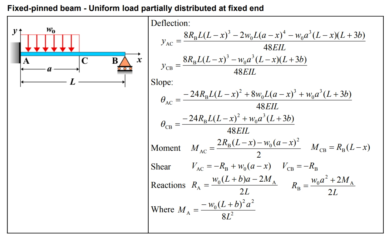
| Deflection \( y_{AC} \) | \[ y_{AC} = \frac{8R_B L(L-x)^3 - 2w_0L(a-x)^4 - w_0a^3(L-x)(L+3b)}{48EI L} \] |
| Deflection \( y_{CB} \) | \[ y_{CB} = \frac{8R_B L(L-x)^3 - w_0a^3(L-x)(L+3b)}{48EI L} \] |
| Slope \( \theta_{AC} \) | \[ \theta_{AC} = \frac{-24R_B L(L-x)^2 + 8w_0L(a-x)^3 + w_0a^3(L+3b)}{48EI L} \] |
| Slope \( \theta_{CB} \) | \[ \theta_{CB} = \frac{-24R_B L(L-x)^2 + w_0a^3(L+3b)}{48EI L} \] |
| Moment \( M_{AC} \) | \[ M_{AC} = \frac{2R_B(L-x) - w_0(a-x)^2}{2} \] |
| Moment \( M_{CB} \) | \[ M_{CB} = R_B(L-x) \] |
| Shear \( V_{AC} \) | \[ V_{AC} = -R_B + w_0(a-x) \] |
| Shear \( V_{CB} \) | \[ V_{CB} = -R_B \] |
| Reaction \( R_A \) | \[ R_A = \frac{w_0(L+b)a - 2M_A}{2L} \] |
| Reaction \( R_B \) | \[ R_B = \frac{w_0a^2 + 2M_A}{2L} \] |
| Where \( M_A \) | \[ M_A = \frac{-w_0(L+b)^2a^2}{8L^2} \] |
Definitions
| Symbol | Physical quantity | Units |
|---|---|---|
| E·I | Flexural rigidity | N·m², Pa·m⁴ |
| y | Deflection or deformation | m |
| θ | Slope, Angle of rotation | - |
| x | Distance from support (origin) | m |
| L | Length of beam (without overhang) | m |
| M | Moment, Bending moment, Couple moment applied | N·m |
| P | Concentrated load, Point load, Concentrated force | N |
| w | Distributed load, Load per unit length | N/m |
| R | Reaction load, reaction force | N |
| V | Shear force, shear | N |