 Home
Home Back
BackFixed-pinned beam - Two equal concentrated loads symmetrically placed Calculator
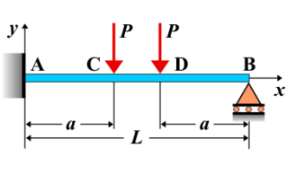
Fixed-Pinned Beam - Two Equal Concentrated Loads Symmetrically Placed
A **fixed-pinned beam** is a beam that is fixed at one end, preventing both translation and rotation, and pinned at the other end, which allows rotation but prevents translation at the pinned support. When **two equal concentrated loads** are symmetrically placed on the beam, they create an even distribution of forces, leading to predictable internal forces and bending moments. The symmetric placement of the loads ensures that the beam experiences symmetrical bending and deflection.
Key Concepts
- Concentrated Loads: A concentrated load is a force applied at a single point along the beam. In this case, two equal concentrated loads are placed symmetrically about the beam’s center.
- Fixed-Pinned Beam: A beam that is fixed at one end, where it cannot translate or rotate, and pinned at the other end, allowing rotation but preventing translation at the pinned support.
- Shear Force: The shear force distribution is influenced by the applied concentrated loads. Since the loads are symmetrically placed, the shear force will vary linearly between the supports, with maximum shear at the fixed end.
- Bending Moment: The bending moment distribution is symmetric due to the symmetrical placement of the loads. The bending moment reaches its maximum at the fixed support, and it gradually decreases as you move towards the pinned support.
- Deflection: The deflection of the beam will be symmetric as well, with the maximum deflection occurring at the center of the beam between the two loads.
Behavior of the Fixed-Pinned Beam
- Reaction Forces:
- The reaction forces at the fixed and pinned supports can be calculated by solving the equilibrium equations for the beam. Due to the symmetry of the loads, the reactions at the supports will be equal and opposite, with each support carrying half of the total applied load.
- At the fixed end, the reaction force will include both a vertical force and a moment. At the pinned end, only a vertical reaction force will exist.
- Shear Force Diagram:
- The shear force diagram will have a triangular shape due to the applied concentrated loads. The shear force is highest at the fixed end and decreases linearly towards the center of the beam, where it is zero.
- The shear force is negative to the left of the center and positive to the right, reaching zero at the location of the second load.
- Bending Moment Diagram:
- The bending moment diagram for this case will be a smooth curve. The moment increases as you move from the pinned support towards the fixed support, reaching a maximum at the fixed end.
- The maximum bending moment occurs at the fixed support and can be calculated as: \[ M_{\text{max}} = \frac{P L}{4} \] where \( P \) is the magnitude of each concentrated load, and \( L \) is the length of the beam.
- After the maximum, the bending moment gradually decreases towards the pinned support.
- Deflection: The deflection of the beam will follow a smooth curve, with the maximum deflection occurring at the center of the beam. The deflection can be calculated using beam deflection formulas: \[ \delta_{\text{max}} = \frac{P L^3}{48 E I} \] where \( P \) is the magnitude of each concentrated load, \( L \) is the length of the beam, \( E \) is the modulus of elasticity, and \( I \) is the moment of inertia of the beam’s cross-section.
Applications
- Structural Engineering: Fixed-pinned beams with symmetrically placed loads are common in structural applications, such as bridges and buildings, where loads are applied evenly across the span.
- Construction: In construction, these types of loadings are typical for beams supporting evenly distributed weight, such as floor beams or roof beams in buildings.
- Mechanical Systems: In mechanical systems, symmetrically placed loads are often encountered in structures like machine frames or beams that support evenly distributed forces.
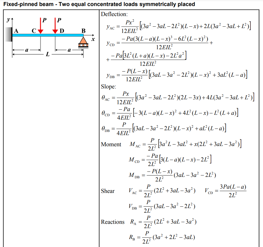
Formula
| Property | Formula |
|---|---|
| Deflection (\(y_{AC}\)) | \(y_{AC} = \frac{Px^2}{12EI L^2} [(3a^2 - 3aL - 2L^2)(L-x) + 2L(3a^2 - 3aL + L^2)]\) |
| Deflection (\(y_{CD}\)) | \(y_{CD} = \frac{-Pa(3(L-a)(L-x)^3 - 6L^2(L-x)^2)}{12EI L^2 a^2} + \frac{-Pa[3L^2(L+a)(L-x) - 2L^2 a]}{12EI L^2}\) |
| Deflection (\(y_{DB}\)) | \(y_{DB} = \frac{-P(L-x)}{12EI L^2} [(3aL - 3a^2 - 2L^2)(L-x)^2 + 3aL^2(L-a)]\) |
| Slope (\(\theta_{AC}\)) | \(\theta_{AC} = \frac{Px}{12EI L^2} [(3a^2 - 3aL - 2L^2)(2L - 3x) + 4L(3a^2 - 3aL + L^2)]\) |
| Slope (\(\theta_{CD}\)) | \(\theta_{CD} = \frac{-Pa}{4EI L^2} [-3(L-a)(L-x)^2 + 4L^2(L-x) - L^2(L+a)]\) |
| Slope (\(\theta_{DB}\)) | \(\theta_{DB} = \frac{P}{4EI L^2} [(3aL - 3a^2 - 2L^2)(L-x)^2 + aL^2(L-a)]\) |
| Moment (\(M_{AC}\)) | \(M_{AC} = \frac{P}{2L^2} [3a^2 L - 3aL^2 + x(2L^2 + 3aL - 3a^2)]\) |
| Moment (\(M_{CD}\)) | \(M_{CD} = \frac{-Pa}{2L^2} [3(L-a)(L-x) - 2L^2]\) |
| Moment (\(M_{DB}\)) | \(M_{DB} = \frac{-P(L-x)}{2L^2} [3aL - 3a^2 - 2L^2]\) |
| Shear (\(V_{AC}\)) | \(V_{AC} = \frac{P}{2L^2} (2L^2 + 3aL - 3a^2)\) |
| Shear (\(V_{CD}\)) | \(V_{CD} = \frac{3Pa(L-a)}{2L^2}\) |
| Shear (\(V_{DB}\)) | \(V_{DB} = \frac{P}{2L^2} (3aL - 3a^2 - 2L^2)\) |
| Reaction (\(R_A\)) | \(R_A = \frac{P}{2L^2} (2L^2 + 3aL - 3a^2)\) |
| Reaction (\(R_B\)) | \(R_B = \frac{P}{2L^2} (3a^2 + 2L^2 - 3aL)\) |
Definitions
| Symbol | Physical quantity | Units |
|---|---|---|
| E·I | Flexural rigidity | N·m², Pa·m⁴ |
| y | Deflection or deformation | m |
| θ | Slope, Angle of rotation | - |
| x | Distance from support (origin) | m |
| L | Length of beam (without overhang) | m |
| M | Moment, Bending moment, Couple moment applied | N·m |
| P | Concentrated load, Point load, Concentrated force | N |
| w | Distributed load, Load per unit length | N/m |
| R | Reaction load, reaction force | N |
| V | Shear force, shear | N |