 Home
Home Back
BackFixed-pinned beam - Couple moment Mo at supported end Calculator
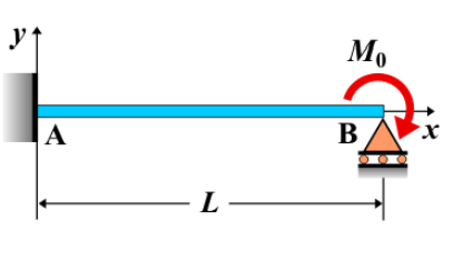
Fixed-Pinned Beam - Couple Moment \( M_0 \) at the Supported End
A **fixed-pinned beam** is a beam that is fixed at one end and pinned at the other. When a **couple moment \( M_0 \)** is applied at the supported end (the pinned end) of the beam, it introduces a moment that causes rotation at that point. This moment does not directly apply any force but induces bending in the beam. The couple moment affects the distribution of internal forces, particularly the bending moment, and influences the overall deflection of the beam.
Key Concepts
- Couple Moment \( M_0 \): A couple moment consists of two equal and opposite forces separated by a distance, creating a rotational effect. Applied to a beam, it creates bending without any net translational force.
- Fixed-Pinned Beam: A beam fixed at one end, preventing both translation and rotation, and pinned at the other, which allows rotation but prevents translation at the pinned support.
- Shear Force: The shear force distribution along the beam is influenced by external loads. A couple moment applied at the pinned support causes a rotational effect, but it does not directly alter the shear force since no net vertical force is applied at the pinned support.
- Bending Moment: The bending moment at the pinned support experiences an instantaneous jump due to the applied couple moment. The bending moment distribution changes, and the moment at any point along the beam will be affected by the couple moment at the supported end.
- Deflection: The deflection of the beam is influenced by the couple moment. The moment induces a rotation at the pinned end, and the deflection varies along the length of the beam depending on its stiffness.
Behavior of the Fixed-Pinned Beam
- Reaction Forces:
- The reaction at the fixed end of the beam will include a vertical reaction force and a moment. The reaction at the pinned end will include only a vertical reaction force, but there will be no vertical reaction due to the applied couple moment.
- The couple moment applied at the pinned end influences the bending moment distribution but does not affect the vertical reactions at the supports.
- Shear Force Diagram:
- The shear force is primarily influenced by any external loads on the beam. Since a couple moment does not apply a vertical force, it does not directly affect the shear force diagram.
- The shear force diagram remains the same as if there were no couple moment applied, with variations due to other external loads, if any.
- Bending Moment Diagram:
- The bending moment at the pinned end experiences a discontinuity due to the applied couple moment \( M_0 \).
- At the pinned end, the bending moment will be equal to \( M_0 \), and it remains constant along the length of the beam, assuming no other external moment or force is applied elsewhere on the beam.
- The bending moment diagram is characterized by a jump at the pinned support, and the moment is constant along the beam as long as the couple is the only moment acting.
- Deflection: The deflection caused by the couple moment \( M_0 \) can be calculated using beam deflection formulas. The beam will rotate at the pinned support, and the deflection at any point along the beam depends on the beam’s material properties, the moment applied, and the beam's geometry. \[ \delta = \frac{M_0 L^2}{2 E I} \] where \( M_0 \) is the applied couple moment, \( L \) is the length of the beam, \( E \) is the modulus of elasticity, and \( I \) is the moment of inertia of the beam’s cross-section.
Applications
- Structural Engineering: This type of loading is used in structural design where rotational forces are applied at the pinned end of beams, such as in frames or structures subjected to wind or seismic forces that induce moments.
- Construction: In construction, beams subjected to couple moments at supports are used in situations where rotation occurs at the supports, such as in structures with rotating equipment or certain types of cantilevered frames.
- Mechanical Systems: Mechanical systems that involve rotating parts, such as gears or shafts, may experience couple moments at specific points, like the ends of shafts or between connecting components.
Formula
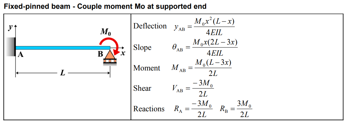
| Property | Formula |
|---|---|
| Deflection (\(y_{AB}\)) | \(y_{AB} = \frac{M_0 x^2 (L-x)}{4EI L}\) |
| Slope (\(\theta_{AB}\)) | \(\theta_{AB} = \frac{M_0 x (2L-3x)}{4EI L}\) |
| Moment (\(M_{AB}\)) | \(M_{AB} = \frac{M_0 (L-3x)}{2L}\) |
| Shear (\(V_{AB}\)) | \(V_{AB} = \frac{-3M_0}{2L}\) |
| Reaction (\(R_A\)) | \(R_A = \frac{-3M_0}{2L}\) |
| Reaction (\(R_B\)) | \(R_B = \frac{3M_0}{2L}\) |
Definitions
| Symbol | Physical quantity | Units |
|---|---|---|
| E·I | Flexural rigidity | N·m², Pa·m⁴ |
| y | Deflection or deformation | m |
| θ | Slope, Angle of rotation | - |
| x | Distance from support (origin) | m |
| L | Length of beam (without overhang) | m |
| M | Moment, Bending moment, Couple moment applied | N·m |
| P | Concentrated load, Point load, Concentrated force | N |
| w | Distributed load, Load per unit length | N/m |
| R | Reaction load, reaction force | N |
| V | Shear force, shear | N |