 Home
Home Back
BackFixed-pinned beam - Couple moment Mo at any point Calculator
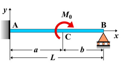
Fixed-Pinned Beam - Couple Moment \( M_0 \) at Any Point
A fixed-pinned beam is a beam that is fixed at one end and pinned at the other. When a couple moment \( M_0 \) is applied at any point along the beam, it causes a moment to be applied at that specific location, affecting the beam's bending and deflection. The couple moment creates a rotational effect without any direct force acting at that point, but it does influence the shear force and bending moment distribution along the beam.
Key Concepts
- Couple Moment \( M_0 \): A couple moment is a pair of equal and opposite forces separated by a distance that generates a rotational effect but no net force. When applied to a beam, it produces a bending effect at the point of application.
- Fixed-Pinned Beam: A beam that is fixed at one end, preventing both translation and rotation, and pinned at the other end, allowing for rotation but preventing translation.
- Shear Force: The shear force varies along the length of the beam. A couple moment does not directly affect the shear force at the point of application, but it influences the shear distribution on either side.
- Bending Moment: The bending moment varies along the beam. A couple moment creates a constant moment at the point of application, influencing the bending moment distribution.
- Deflection: The deflection of the beam is influenced by the applied couple moment and the beam's properties. The deflection varies along the length of the beam due to the moment.
Behavior of the Fixed-Pinned Beam
- Reaction Forces:
- The reaction forces at the supports can be determined by solving the equilibrium equations for the beam. The fixed end will carry both a vertical reaction and a moment, while the pinned end will only carry a vertical reaction.
- While a couple moment does not directly introduce a vertical load, it alters the bending moment distribution along the beam.
- Shear Force Diagram:
- The shear force distribution is not directly affected by the applied couple moment, as the moment does not produce a net force. Therefore, the shear force is primarily determined by any other external loads acting on the beam.
- Bending Moment Diagram:
- The bending moment at the point where the couple moment \( M_0 \) is applied experiences an instantaneous jump. On either side of the point of application, the bending moment is influenced by the couple moment.
- The moment is constant before and after the location of the applied couple. The bending moment diagram will have a discontinuity at the point where the couple is applied.
- The bending moment at any point \( x \) along the beam is given by: \[ M(x) = M_{\text{left}} + M_0 \] where \( M_{\text{left}} \) is the bending moment to the left of the applied couple, and \( M_0 \) is the magnitude of the couple moment.
- Deflection: The deflection caused by a couple moment can be calculated using beam deflection formulas, which account for the moment’s influence on the beam. The deflection will be greatest at the location of the applied moment, and its exact value depends on the beam’s length, moment of inertia, and modulus of elasticity. \[ \delta = \frac{M_0 L^2}{2 E I} \] where \( M_0 \) is the applied couple moment, \( L \) is the length of the beam, \( E \) is the modulus of elasticity, and \( I \) is the moment of inertia of the beam’s cross-section.
Applications
- Structural Engineering: This loading condition is often used to model moments applied at a specific location in beams, such as at joints or where rotating machinery is mounted.
- Construction: Fixed-pinned beams with applied couple moments are found in construction scenarios where beams are subjected to twisting moments, such as in structural frames or beams supporting rotating equipment.
- Mechanical Systems: Mechanical systems that involve rotating shafts or parts that apply moment loads, such as motor drives, turbines, or gears, often experience couple moments at specific points along the beam or shaft.
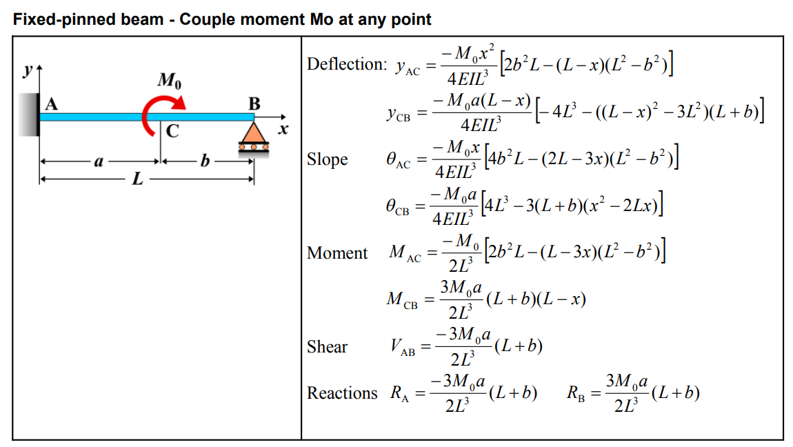
Formula
Definitions
| Property | Formula |
|---|---|
| Deflection (\(y_{AC}\)) | \(y_{AC} = \frac{-M_0 x}{4EI L^3} \left[ 2b^2 L - (L-x)(L^2 - b^2) \right]\) |
| Deflection (\(y_{CB}\)) | \(y_{CB} = \frac{-M_0 a(L-x)}{4EI L^3} \left[ -4L^3 - ((L-x)^2 - 3L^2)(L+b) \right]\) |
| Slope (\(\theta_{AC}\)) | \(\theta_{AC} = \frac{-M_0 x}{4EI L^3} \left[ 4b^2 L - (2L-3x)(L^2 - b^2) \right]\) |
| Slope (\(\theta_{CB}\)) | \(\theta_{CB} = \frac{-M_0 a}{4EL^3} \left[ 4L^3 - 3(L+b)(x^2 - 2Lx) \right]\) |
| Moment (\(M_{AC}\)) | \(M_{AC} = \frac{-M_0}{2L^3} \left[ 2b^2 L - (L-3x)(L^2 - b^2) \right]\) |
| Moment (\(M_{CB}\)) | \(M_{CB} = \frac{3M_0 a}{2L^3} (L+b)(L-x)\) |
| Shear (\(V_{AB}\)) | \(V_{AB} = \frac{-3M_0 a}{2L^3} (L+b)\) |
| Reaction (\(R_A\)) | \(R_A = \frac{-3M_0 a}{2L^3} (L+b)\) |
| Reaction (\(R_B\)) | \(R_B = \frac{3M_0 a}{2L^3} (L+b)\) |
Definitions
| Symbol | Physical quantity | Units |
|---|---|---|
| E·I | Flexural rigidity | N·m², Pa·m⁴ |
| y | Deflection or deformation | m |
| θ | Slope, Angle of rotation | - |
| x | Distance from support (origin) | m |
| L | Length of beam (without overhang) | m |
| M | Moment, Bending moment, Couple moment applied | N·m |
| P | Concentrated load, Point load, Concentrated force | N |
| w | Distributed load, Load per unit length | N/m |
| R | Reaction load, reaction force | N |
| V | Shear force, shear | N |