 Home
Home Back
BackFixed-pinned beam - Concentrated load at center Calculator
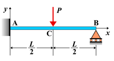
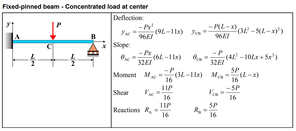
Fixed-Pinned Beam - Concentrated Load at Center
A **fixed-pinned beam** is a beam that is fixed at one end and pinned at the other. When a **concentrated load** is applied at the center of the beam, it induces shear forces, bending moments, and deflection. The response of the beam is symmetrical because the load is applied centrally, and the reactions at both supports can be determined based on the symmetry of the system.
Key Concepts
- Concentrated Load: A load that is applied at a specific point along the beam. When the load is at the center of the beam, it creates symmetric effects in terms of shear force and bending moment.
- Fixed-Pinned Beam: A beam that is fixed at one end, preventing both translation and rotation, and pinned at the other end, allowing for rotation but preventing translation.
- Shear Force: The shear force varies along the length of the beam, with the maximum shear force occurring at the fixed support and decreasing linearly toward the pinned support.
- Bending Moment: The bending moment is maximum at the center of the beam and decreases toward the supports, being zero at both the fixed and pinned ends.
- Deflection: The deflection of the beam is greatest at the center where the load is applied, and it decreases symmetrically toward the supports.
Behavior of the Fixed-Pinned Beam
- Reaction Forces:
- The total concentrated load \( P \) applied at the center of the beam is symmetrically distributed between the two supports. Therefore, each support reaction is equal to half the load, i.e., \( R_A = R_B = \frac{P}{2} \).
- The reactions can be determined using equilibrium equations (sum of vertical forces and moments) for the fixed-pinned beam system.
- Shear Force Diagram:
- The shear force is constant between the two reactions and decreases linearly from the supports toward the center.
- At the center, the shear force is zero, and it changes sign from one side of the load to the other.
- The shear force diagram consists of two horizontal sections (constant shear) on either side of the load, with a jump at the location of the applied load: \[ V(x) = \frac{P}{2} \] for the left side and \[ V(x) = -\frac{P}{2} \] for the right side of the beam.
- Bending Moment Diagram:
- The bending moment is zero at both the fixed and pinned ends and reaches a maximum at the center of the beam.
- The bending moment diagram is a triangle with the peak occurring at the center and the slope of the diagram changing from positive to negative as you move from the supports toward the center.
- The maximum bending moment occurs at the center and is given by: \[ M_{\text{max}} = \frac{P L}{4} \] where \( P \) is the concentrated load and \( L \) is the length of the beam.
- Deflection: The deflection is maximum at the center of the beam, directly beneath the applied load. The deflection at any point along the beam can be calculated using beam deflection formulas, and the maximum deflection occurs at the center: \[ \delta_{\text{max}} = \frac{P L^3}{48 E I} \] where \( P \) is the concentrated load, \( L \) is the length of the beam, \( E \) is the modulus of elasticity, and \( I \) is the moment of inertia of the beam’s cross-section.
Applications
- Structural Engineering: This condition is common in beams subjected to point loads at the center, such as bridges, floors, and structural elements where a load is applied at the midpoint.
- Construction: Used in structural analysis for beams in buildings, bridges, and other systems where loads are applied at or near the center of the beam span.
- Mechanical Systems: Found in mechanical applications where beams or shafts experience concentrated loads at the center, such as in rotating systems or support beams for heavy equipment.
Formula
Definitions
| Symbol | Physical quantity | Units |
|---|---|---|
| E·I | Flexural rigidity | N·m², Pa·m⁴ |
| y | Deflection or deformation | m |
| θ | Slope, Angle of rotation | - |
| x | Distance from support (origin) | m |
| L | Length of beam (without overhang) | m |
| M | Moment, Bending moment, Couple moment applied | N·m |
| P | Concentrated load, Point load, Concentrated force | N |
| w | Distributed load, Load per unit length | N/m |
| R | Reaction load, reaction force | N |
| V | Shear force, shear | N |