 Home
Home Back
BackFixed-pinned beam - Concentrated load at any point Calculator
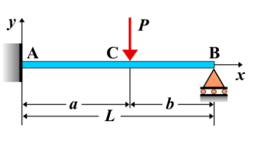
Fixed-Pinned Beam - Concentrated Load at Any Point
A **fixed-pinned beam** is a beam that is fixed at one end and pinned at the other. This configuration allows for rotation at the pinned support but prevents translation. When a **concentrated load** is applied at any point along the beam, it causes shear forces, bending moments, and deflection, and the beam responds based on the location of the load.
Key Concepts
- Concentrated Load: A load applied at a specific point along the beam, creating localized effects in shear force and bending moment.
- Fixed-Pinned Beam: A beam that is fixed at one end, preventing both translation and rotation, and pinned at the other end, allowing for rotation but no translation at the pinned support.
- Shear Force: The shear force varies along the length of the beam, with a step change at the location of the applied load. The shear force is constant on either side of the load point until it reaches the supports.
- Bending Moment: The bending moment has a linear distribution on either side of the applied load and changes slope at the load location. The maximum bending moment typically occurs at or near the location of the load.
- Deflection: The deflection of the beam is affected by the applied load, and the beam bends more near the location of the load, with the maximum deflection occurring at a point depending on the load position.
Behavior of the Fixed-Pinned Beam
- Reaction Forces:
- The total concentrated load \( P \) applied at a point causes reaction forces at both supports.
- By solving the equilibrium equations (sum of forces and moments), the reactions at the fixed and pinned supports can be found. The reaction at the pinned support is typically vertical, while the reaction at the fixed support has both vertical and moment components.
- Shear Force Diagram:
- The shear force has a step change at the point where the load is applied.
- The shear force is constant between the load and the pinned support, and there is a jump in the shear force magnitude at the location of the load.
- On the side of the fixed support, the shear force changes in response to the applied load, and it can be expressed as: \[ V(x) = R_A - P \] where \( R_A \) is the reaction at the fixed support and \( P \) is the applied load.
- Bending Moment Diagram:
- The bending moment varies linearly between the supports, with a slope change at the location of the applied load.
- The maximum bending moment typically occurs at the point of load application or between the load and the supports.
- The bending moment at any point along the beam can be expressed as: \[ M(x) = R_A \cdot x - P \cdot (x - a) \] where \( x \) is the distance from the fixed support, \( a \) is the distance from the fixed support to the location of the load, and \( P \) is the applied load.
- Deflection: The deflection of the beam at any point can be calculated using beam deflection formulas that account for the applied load and the beam's properties. The maximum deflection occurs at a location based on the load and the beam stiffness. \[ \delta_{\text{max}} = \frac{P \cdot L^3}{3 E I} \] where \( P \) is the applied load, \( L \) is the beam length, \( E \) is the modulus of elasticity, and \( I \) is the moment of inertia of the beam’s cross-section.
Applications
- Structural Engineering: Common in beams subjected to point loads, such as beams in bridges, floors, and structural frameworks where localized loads are applied.
- Construction: Fixed-pinned beams are used in construction where one end is fully fixed and the other is allowed to rotate, for example, in floor beams and bridge spans.
- Mechanical Systems: Found in mechanical systems where concentrated loads are applied, such as shafts, supports, or machine parts subjected to point loads or impacts.
Formula
| Quantity | Formula |
|---|---|
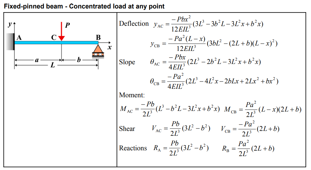
| Deflection \(y_{AC}\) | \[ y_{AC} = \frac{-Pbx^2}{12EI L^3} \left( 3L^3 - 3b^2L - 3L^2x + b^2x \right) \] |
| Deflection \(y_{CB}\) | \[ y_{CB} = \frac{-Pa^2(L-x)}{12EI L^3} \left( 3bL^2 - (2L + b)(L-x)^2 \right) \] |
| Slope \(\theta_{AC}\) | \[ \theta_{AC} = \frac{-Pbx}{4EI L^3} \left( 2L^3 - 2b^2L - 3L^2x + b^2x \right) \] |
| Slope \(\theta_{CB}\) | \[ \theta_{CB} = \frac{-Pa^2}{4EI L^3} \left( 2L^3 - 4L^2x - 2bLx + 2Lx^2 + bx^2 \right) \] |
| Moment \(M_{AC}\) | \[ M_{AC} = \frac{-Pb}{2L^3} \left( L^3 - b^2L - 3L^2x + b^2x \right) \] |
| Moment \(M_{CB}\) | \[ M_{CB} = \frac{Pa^2}{2L^3} (L-x)(2L+b) \] |
| Shear \(V_{AC}\) | \[ V_{AC} = \frac{Pb}{2L^3} (3L^2 - b^2) \] |
| Shear \(V_{CB}\) | \[ V_{CB} = \frac{-Pa^2}{2L^3} (2L + b) \] |
| Reaction \(R_A\) | \[ R_A = \frac{Pb}{2L^3} (3L^2 - b^2) \] |
| Reaction \(R_B\) | \[ R_B = \frac{Pa^2}{2L^3} (2L + b) \] |
Definitions
| Symbol | Physical quantity | Units |
|---|---|---|
| E·I | Flexural rigidity | N·m², Pa·m⁴ |
| y | Deflection or deformation | m |
| θ | Slope, Angle of rotation | - |
| x | Distance from support (origin) | m |
| L | Length of beam (without overhang) | m |
| M | Moment, Bending moment, Couple moment applied | N·m |
| P | Concentrated load, Point load, Concentrated force | N |
| w | Distributed load, Load per unit length | N/m |
| R | Reaction load, reaction force | N |
| V | Shear force, shear | N |