 Home
Home Back
BackFixed-fixed beam - Uniformly distributed load Calculator
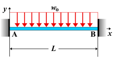
Fixed-Fixed Beam - Uniformly Distributed Load
A **fixed-fixed beam** is a beam that is rigidly supported at both ends. When a **uniformly distributed load** is applied along the entire length of the beam, it causes the beam to bend, develop shear forces, and experience deflection. The load is distributed evenly along the length of the beam, which results in a characteristic bending and shear response.
Key Concepts
- Uniformly Distributed Load: A load that is applied along the entire length of the beam, with a constant intensity \( w \), acting over the full span of the beam.
- Fixed-Fixed Beam: A beam that is fixed at both ends, meaning it cannot move or rotate at either support.
- Shear Force: The shear force along the beam varies and has a triangular distribution. The maximum shear force occurs at the supports.
- Bending Moment: The bending moment is zero at both fixed ends and varies along the length of the beam. It reaches a maximum at the midpoint of the beam.
- Deflection: The deflection is also maximum at the midpoint of the beam, and it varies along the length due to the uniform distribution of the load.
Behavior of the Fixed-Fixed Beam
- Reaction Forces:
- The total load applied by the uniform distribution is \( w \times L \), where \( w \) is the load intensity and \( L \) is the length of the beam.
- The reaction forces at both fixed supports can be determined by solving equilibrium equations for the beam. Each support will carry half of the total load due to the symmetry of the loading condition.
- Shear Force Diagram:
- The shear force varies linearly along the length of the beam, starting at a maximum value at one support and decreasing linearly to the maximum shear force at the other support.
- The shear force is greatest at the supports and is zero at the midpoint of the beam.
- The shear force at any point along the beam can be expressed as: \[ V(x) = \frac{w L}{2} - w x \] where \( x \) is the distance from the left support, \( w \) is the load intensity, and \( L \) is the length of the beam.
- Bending Moment Diagram:
- The bending moment is zero at both fixed ends, as there is no rotational displacement at the supports.
- The bending moment increases from zero at the left support, reaches a maximum at the midpoint of the beam, and then decreases to zero at the right support.
- The maximum bending moment occurs at the midpoint and is given by: \[ M_{\text{max}} = \frac{w L^2}{8} \] where \( w \) is the uniform load intensity and \( L \) is the length of the beam.
- Deflection: The deflection of a fixed-fixed beam subjected to a uniformly distributed load can be calculated using beam deflection formulas. The maximum deflection occurs at the midpoint of the beam. \[ \delta_{\text{max}} = \frac{5 w L^4}{384 E I} \] where \( w \) is the uniform load intensity, \( L \) is the length of the beam, \( E \) is the modulus of elasticity, and \( I \) is the moment of inertia of the beam's cross-section.
Applications
- Structural Engineering: This condition is common in beams subjected to evenly distributed loads, such as floor beams, bridge decks, and roof beams where the load is evenly spread along the length of the structure.
- Construction: Fixed-fixed beams are used in buildings, bridges, and other structures where the load is uniformly distributed across the beam span.
- Mechanical Systems: Uniformly distributed loads are encountered in mechanical components such as shafts, supports, and components experiencing evenly spread pressure or force.
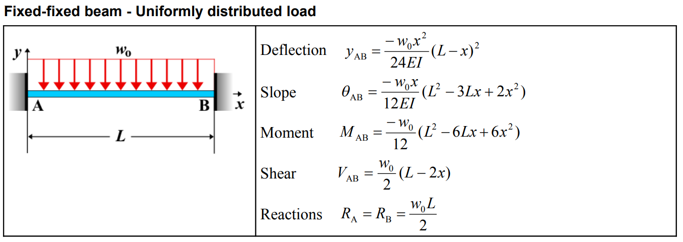
Formula
| Quantity | Formula |
|---|---|
| Deflection \(y_{AB}\) | \[ y_{AB} = \frac{-w_0 x^2 (L - x)^2}{24EI} \] |
| Slope \(\theta_{AB}\) | \[ \theta_{AB} = \frac{-w_0 x}{12EI} \left( L^2 - 3Lx + 2x^2 \right) \] |
| Moment \(M_{AB}\) | \[ M_{AB} = \frac{-w_0}{12} \left( L^2 - 6Lx + 6x^2 \right) \] |
| Shear \(V_{AB}\) | \[ V_{AB} = \frac{w_0}{2} \left( L - 2x \right) \] |
| Reactions \(R_A\) and \(R_B\) | \[ R_A = R_B = \frac{w_0 L}{2} \] |
Definitions
| Symbol | Physical quantity | Units |
|---|---|---|
| E·I | Flexural rigidity | N·m², Pa·m⁴ |
| y | Deflection or deformation | m |
| θ | Slope, Angle of rotation | - |
| x | Distance from support (origin) | m |
| L | Length of beam (without overhang) | m |
| M | Moment, Bending moment, Couple moment applied | N·m |
| P | Concentrated load, Point load, Concentrated force | N |
| w | Distributed load, Load per unit length | N/m |
| R | Reaction load, reaction force | N |
| V | Shear force, shear | N |