 Home
Home Back
BackFixed-fixed beam - Uniform load partially distributed Calculator
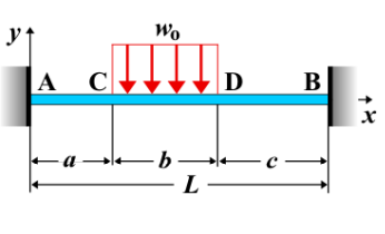
Fixed-Fixed Beam - Uniform Load Partially Distributed
A fixed-fixed beam is a beam that is rigidly supported at both ends, with no displacement or rotation allowed at the supports. When a **uniform load** is applied partially along the beam, starting from one end, it creates bending, shear forces, and deflections along the beam. The load distribution is uniform but applies only over a portion of the beam's length.
Key Concepts
- Uniform Load: A distributed load applied with constant intensity \( w \), but only over a part of the beam's length, starting from one end and extending a distance \( a \) along the beam.
- Fixed-Fixed Beam: A beam that is rigidly fixed at both ends, preventing both translational and rotational displacement at the supports.
- Shear Force: The shear force varies along the length of the beam, with a constant value over the region where the uniform load is applied. The shear force will change slope at the point where the load stops, and it is zero at the center of the beam.
- Bending Moment: The bending moment distribution is influenced by the uniform load and is highest at the location where the load is applied, decreasing towards the fixed supports.
- Deflection: The deflection is influenced by the applied load, the stiffness of the beam, and the portion of the beam over which the load is distributed. The maximum deflection typically occurs at the location of the applied load.
Behavior of the Fixed-Fixed Beam
- Reaction Forces:
- The total applied load due to the uniform distribution is \( w \times a \), where \( w \) is the load intensity and \( a \) is the length over which the load is applied.
- The reactions at the supports are determined by solving the equilibrium equations for the beam, considering both the vertical forces and the moments caused by the load distribution.
- Shear Force Diagram:
- The shear force is constant over the length of the applied uniform load and changes at the point where the load ends. After the load stops, the shear force varies linearly towards the right support.
- The shear force is maximum at the left support and decreases until the load ends, where the slope of the shear force diagram changes.
- Bending Moment Diagram:
- The bending moment increases from zero at the left support, reaching a maximum at the point where the load ends, and then decreases as you move toward the right support.
- The maximum bending moment occurs at the location where the load ends and can be calculated as: \[ M_{\text{max}} = \frac{w a^2}{2} \] where \( w \) is the uniform load intensity and \( a \) is the length of the applied load portion of the beam.
- The bending moment is zero at both fixed supports, as the beam cannot rotate or translate at these points.
- Deflection: The deflection varies along the length of the beam and is highest where the bending moment is maximum. The maximum deflection typically occurs at or near the point where the load is applied. The deflection at any point along the beam can be calculated using standard beam deflection formulas. \[ \delta_{\text{max}} = \frac{w a^4}{8 E I} \] where \( w \) is the uniform load intensity, \( a \) is the length of the loaded portion of the beam, \( E \) is the modulus of elasticity, and \( I \) is the moment of inertia of the beam's cross-section.
Applications
- Structural Engineering: Common in beams subjected to partial loads, such as bridges, building beams, and platforms with specific load applications.
- Construction: Relevant in analyzing beams subjected to varying loads in parts of buildings or structural systems, such as floors with concentrated loads.
- Mechanical Systems: Found in mechanical systems where loads are applied unevenly along components, such as shafts or beams supporting machinery parts or equipment.
Formula
| Quantity | Formula |
|---|---|
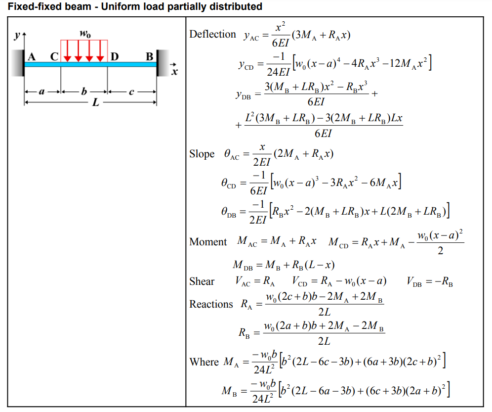
| Deflection \(y_{AC}\) | \[ y_{AC} = \frac{x^2}{6EI}(3M_A + R_A x) \] |
| Deflection \(y_{CD}\) | \[ y_{CD} = \frac{-1}{24EI} \left[ w_0 (x - a)^4 - 4R_A x^3 - 12M_A x^2 \right] \] |
| Deflection \(y_{DB}\) | \[ y_{DB} = \frac{3(M_B + L R_B)x^2 - R_B x^3}{6EI} + \frac{L^2(3M_B + LR_B) - 3(2M_B + LR_B)Lx}{6EI} \] |
| Slope \(\theta_{AC}\) | \[ \theta_{AC} = \frac{x}{2EI}(2M_A + R_A x) \] |
| Slope \(\theta_{CD}\) | \[ \theta_{CD} = \frac{-1}{6EI} \left[ w_0(x - a)^3 - 3R_A x^2 - 6M_A x \right] \] |
| Slope \(\theta_{DB}\) | \[ \theta_{DB} = \frac{-1}{2EI} \left[ R_B x^2 - 2(M_B + LR_B)x + L(2M_B + LR_B) \right] \] |
| Moment \(M_{AC}\) | \[ M_{AC} = M_A + R_A x \] |
| Moment \(M_{CD}\) | \[ M_{CD} = R_A x + M_A - \frac{w_0 (x - a)^2}{2} \] |
| Moment \(M_{DB}\) | \[ M_{DB} = M_B + R_B (L - x) \] |
| Shear \(V_{AC}\) | \[ V_{AC} = R_A \] |
| Shear \(V_{CD}\) | \[ V_{CD} = R_A - w_0 (x - a) \] |
| Shear \(V_{DB}\) | \[ V_{DB} = -R_B \] |
| Reactions \(R_A\) | \[ R_A = \frac{w_0(2c + b)b - 2M_A + 2M_B}{2L} \] |
| Reactions \(R_B\) | \[ R_B = \frac{w_0(2a + b)b + 2M_A - 2M_B}{2L} \] |
| Where \(M_A\) | \[ M_A = \frac{-w_0 b}{24L^2} \left[ b^2(2L - 6c - 3b) + (6a + 3b)(2c + b)^2 \right] \] |
| Where \(M_B\) | \[ M_B = \frac{-w_0 b}{24L^2} \left[ b^2(2L - 6a - 3b) + (6c + 3b)(2a + b)^2 \right] \] |
Definitions
| Symbol | Physical quantity | Units |
|---|---|---|
| E·I | Flexural rigidity | N·m², Pa·m⁴ |
| y | Deflection or deformation | m |
| θ | Slope, Angle of rotation | - |
| x | Distance from support (origin) | m |
| L | Length of beam (without overhang) | m |
| M | Moment, Bending moment, Couple moment applied | N·m |
| P | Concentrated load, Point load, Concentrated force | N |
| w | Distributed load, Load per unit length | N/m |
| R | Reaction load, reaction force | N |
| V | Shear force, shear | N |