 Home
Home Back
BackFixed-fixed beam - Uniform load partially distributed at left end II Calculator
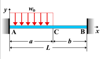
Fixed-Fixed Beam - Uniform Load Partially Distributed at Left End II
A fixed-fixed beam is a beam that is rigidly supported at both ends. When a **uniform load** is applied partially at the left end, this load distribution creates bending, shear force, and deflection along the beam. This type of load is typically used when the load is not distributed evenly along the entire beam, but only across a specific portion near one end.
Key Concepts
- Uniform Load: A distributed load with constant intensity \( w \), applied over a partial length \( a \) of the beam, starting from the left end and extending to a point along the beam.
- Fixed-Fixed Beam: A beam that is rigidly supported at both ends, meaning no movement or rotation is allowed at the supports.
- Shear Force: The shear force varies along the beam. It increases linearly at the start of the loaded portion and then continues until the end of the load distribution. After the load ends, the shear force distribution changes slope at the point where the load stops.
- Bending Moment: The bending moment increases in a nonlinear manner as the beam moves from the fixed left support to the point where the load ends. The maximum bending moment occurs at the point of application of the load.
- Deflection: The deflection is influenced by the magnitude of the applied load, the length of the load distribution, and the beam's stiffness. The maximum deflection typically occurs at the point of maximum bending moment.
Behavior of the Fixed-Fixed Beam
- Reaction Forces:
- The total applied load due to the uniform distribution is \( w \times a \), where \( w \) is the load intensity and \( a \) is the length over which the load is applied.
- The reactions at the supports can be determined by solving equilibrium equations for the beam, taking into account both the vertical forces and the moments caused by the load distribution.
- Shear Force Diagram:
- The shear force increases linearly at the left end, reaches a peak, and then drops at the point where the load ends. After the load stops, the shear force varies linearly until it reaches the right support.
- At the fixed support, the shear force is highest, while the shear force is zero where the load ends.
- Bending Moment Diagram:
- The bending moment starts at zero at the fixed support and increases as you move along the beam to the end of the load. The maximum bending moment occurs at the location where the load is applied.
- The bending moment decreases after the load stops, tapering off towards the right support.
- The maximum bending moment is at the end of the loaded region, and it can be calculated as: \[ M_{\text{max}} = \frac{w a^2}{2} \] where \( w \) is the uniform load intensity and \( a \) is the length of the loaded portion of the beam.
- Deflection: The deflection can be calculated using standard beam deflection formulas. The deflection at the left end will be influenced by the applied load and the stiffness of the beam. The maximum deflection typically occurs near the left support or the point of the applied load. \[ \delta_{\text{max}} = \frac{w a^4}{8 E I} \] where \( w \) is the uniform load intensity, \( a \) is the length of the loaded portion, \( E \) is the modulus of elasticity, and \( I \) is the moment of inertia of the beam's cross-section.
Applications
- Structural Engineering: Common in beams subjected to partial load conditions, such as beams in bridges or floors supporting only specific sections of a building or structure.
- Construction: Relevant in analyzing beams with uneven loading, such as overhanging floors or beams under specific point loads.
- Mechanical Systems: Found in mechanical components experiencing varying pressure or load distributions, such as parts of machinery or equipment with uneven weight distribution.
Formula
| Quantity | Formula |
|---|---|
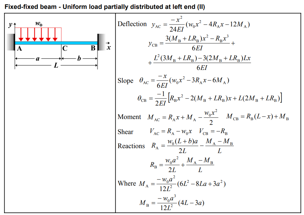
| Deflection \(y_{AC}\) | \[ y_{AC} = \frac{-x^2}{24EI} \left(w_0 x^2 - 4R_A x - 12M_A \right) \] |
| Deflection \(y_{CB}\) | \[ y_{CB} = \frac{3(M_B + L R_B)x^2 - R_B x^3}{6EI} + \frac{L^2 (3M_B + LR_B) - 3(2M_B + LR_B)Lx}{6EI} \] |
| Slope \(\theta_{AC}\) | \[ \theta_{AC} = \frac{-x}{6EI} \left(w_0 x^2 - 3R_A x - 6M_A \right) \] |
| Slope \(\theta_{CB}\) | \[ \theta_{CB} = \frac{-1}{2EI} \left[ R_B x^2 - 2(M_B + L R_B)x + L(2M_B + L R_B) \right] \] |
| Moment \(M_{AC}\) | \[ M_{AC} = R_A x + M_A - \frac{w_0 x^2}{2} \] |
| Moment \(M_{CB}\) | \[ M_{CB} = R_B (L - x) + M_B \] |
| Shear \(V_{AC}\) | \[ V_{AC} = R_A - w_0 x \] |
| Shear \(V_{CB}\) | \[ V_{CB} = -R_B \] |
| Reaction \(R_A\) | \[ R_A = \frac{w_0 (L + b) a^2}{2L} - \frac{M_A + M_B}{L} \] |
| Reaction \(R_B\) | \[ R_B = \frac{w_0 a^2}{2L} + \frac{M_A - M_B}{L} \] |
| Where \(M_A\) | \[ M_A = \frac{-w_0 a^2}{12L^2} \left(6L^2 - 8La + 3a^2 \right) \] |
| Where \(M_B\) | \[ M_B = \frac{-w_0 a^3}{12L^2} \left(4L - 3a \right) \] |
Definitions
| Symbol | Physical quantity | Units |
|---|---|---|
| E·I | Flexural rigidity | N·m², Pa·m⁴ |
| y | Deflection or deformation | m |
| θ | Slope, Angle of rotation | - |
| x | Distance from support (origin) | m |
| L | Length of beam (without overhang) | m |
| M | Moment, Bending moment, Couple moment applied | N·m |
| P | Concentrated load, Point load, Concentrated force | N |
| w | Distributed load, Load per unit length | N/m |
| R | Reaction load, reaction force | N |
| V | Shear force, shear | N |