 Home
Home Back
BackFixed-fixed beam - Uniform load partially distributed at left end I Calculator
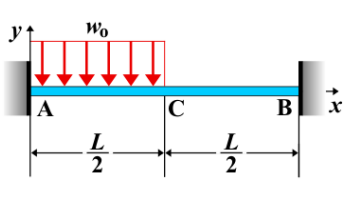
Fixed-Fixed Beam - Uniform Load Partially Distributed at Left End
A fixed-fixed beam is a beam that is rigidly supported at both ends. When a **uniform load** is applied over a partial length of the beam at the left end, the load causes bending, shear force, and deflection. The load distribution is uniform, but it only applies over part of the beam's length, creating a non-uniform response along the beam.
Key Concepts
- Uniform Load: A distributed load applied with a constant intensity \( w \), but only over a portion of the beam's length starting from the left end.
- Fixed-Fixed Beam: A beam that is rigidly supported at both ends, preventing any translational or rotational displacements at the supports.
- Shear Force: The shear force varies along the beam, with a change in slope at the point where the uniform load ends. The shear force is highest near the fixed end where the load is applied.
- Bending Moment: The bending moment is influenced by the uniform load and increases from the left end up to the point where the load ends, before tapering off towards the right fixed end.
- Deflection: The deflection varies along the length of the beam, with the maximum deflection occurring near the left end where the load is applied.
Behavior of the Fixed-Fixed Beam
- Reaction Forces:
- The total load applied by the uniform distribution is \( w \times a \), where \( w \) is the load intensity and \( a \) is the length over which the load is applied.
- The reaction forces at the supports are determined by equilibrium equations, considering the total load and the moments created by the load distribution.
- Shear Force Diagram:
- The shear force is constant along the length of the uniformly loaded portion, then drops at the point where the load ends and continues linearly to the fixed end.
- At the right end of the beam, the shear force is balanced by the reaction force at the right support.
- Bending Moment Diagram:
- The bending moment increases from the left end, peaking at the point where the load ends, and decreases toward the fixed support at the right end.
- The bending moment at the left end is nonzero, while at the right end, it is zero because the fixed support prevents any rotation.
- The maximum bending moment occurs at the end of the uniformly loaded region and can be calculated as: \[ M_{\text{max}} = \frac{w a^2}{2} \] where \( w \) is the uniform load intensity and \( a \) is the length of the loaded portion of the beam.
- Deflection: The deflection at any point along the beam can be calculated using standard beam deflection formulas. The maximum deflection typically occurs at the left end and is influenced by the magnitude of the applied load and the length of the beam. \[ \delta_{\text{max}} = \frac{w a^4}{8 E I} \] where \( w \) is the load intensity, \( a \) is the length over which the load is applied, \( E \) is the modulus of elasticity, and \( I \) is the moment of inertia of the beam's cross-section.
Applications
- Structural Engineering: Common in beams subjected to loads from structures or equipment that only partially cover the beam length, such as overhanging balconies or beams supporting uneven loads.
- Construction: Relevant in beams supporting non-uniform loads, such as portions of roofs or floors with varying loading conditions.
- Mechanical Systems: Found in mechanical systems with partially distributed loads, such as components experiencing varying pressure or force distribution along their length.
Formula

| Quantity | Expression |
|---|---|
| Deflection \(y_{AC}\) | \[ y_{AC} = \frac{-x^2}{24EI} \left(w_0 x^2 - 4R_A x - 12M_A \right) \] |
| Deflection \(y_{CB}\) | \[ y_{CB} = \frac{3(M_B + L R_B)x^2 - R_B x^3}{6EI} + \frac{L^2 (3M_B + LR_B) - 3(2M_B + LR_B)Lx}{6EI} \] |
| Slope \(\theta_{AC}\) | \[ \theta_{AC} = \frac{-x}{6EI} \left(w_0 x^2 - 3R_A x - 6M_A \right) \] |
| Slope \(\theta_{CB}\) | \[ \theta_{CB} = \frac{-1}{2EI} \left[ R_B x^2 - 2(M_B + L R_B)x + L(2M_B + L R_B) \right] \] |
| Moment \(M_{AC}\) | \[ M_{AC} = R_A x + M_A - \frac{w_0 x^2}{2} \] |
| Moment \(M_{CB}\) | \[ M_{CB} = R_B (L - x) + M_B \] |
| Shear \(V_{AC}\) | \[ V_{AC} = R_A - w_0 x \] |
| Shear \(V_{CB}\) | \[ V_{CB} = -R_B \] |
| Reaction \(R_A\) | \[ R_A = \frac{3w_0 L}{8} - \frac{M_A - M_B}{L} \] |
| Reaction \(R_B\) | \[ R_B = \frac{w_0 L}{8} + \frac{M_A - M_B}{L} \] |
| Where \(M_A\) | \[ M_A = \frac{-11w_0 L^2}{192} \] |
| Where \(M_B\) | \[ M_B = \frac{-5w_0 L^2}{192} \] |
Definitions
| Symbol | Physical quantity | Units |
|---|---|---|
| E·I | Flexural rigidity | N·m², Pa·m⁴ |
| y | Deflection or deformation | m |
| θ | Slope, Angle of rotation | - |
| x | Distance from support (origin) | m |
| L | Length of beam (without overhang) | m |
| M | Moment, Bending moment, Couple moment applied | N·m |
| P | Concentrated load, Point load, Concentrated force | N |
| w | Distributed load, Load per unit length | N/m |
| R | Reaction load, reaction force | N |
| V | Shear force, shear | N |