 Home
Home Back
BackFixed-fixed beam - Couple moment Mo at center Calculator
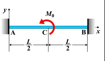
Fixed-Fixed Beam - Couple Moment \( M_0 \) at Center
A fixed-fixed beam is a beam that is rigidly supported at both ends, preventing rotation and translation. When a couple moment \( M_0 \) is applied at the center of the beam, it generates bending moments along the beam without affecting the shear force distribution. The couple moment induces a rotational effect but does not produce a net force.
Key Concepts
- Couple Moment \( M_0 \): A pair of equal and opposite forces whose lines of action do not coincide, causing a rotational effect without a net force. When applied at the center of the beam, the couple moment generates bending without changing the shear force distribution.
- Fixed-Fixed Beam: A beam supported at both ends with fixed supports that prevent any displacement or rotation at the supports.
- Shear Force: The shear force remains constant along the length of the beam and is unaffected by the application of a couple moment because a couple moment has no net force.
- Bending Moment: The bending moment varies along the beam and shows a discontinuity at the point of application of the couple moment. The bending moment reaches a maximum value at the center of the beam, where the couple is applied.
- Deflection: The deflection is influenced by the magnitude and location of the applied couple moment. It creates a curvature in the beam, and the maximum deflection typically occurs at the center.
Behavior of the Fixed-Fixed Beam
- Reaction Forces:
- The reaction forces at both fixed ends of the beam remain unchanged by the couple moment because the couple moment does not produce any net force. The reactions at the supports are determined by the equilibrium of forces and moments.
- Shear Force Diagram:
- The shear force remains constant along the length of the beam, as the couple moment does not affect the net force applied to the beam.
- The shear force diagram is flat, with a constant value along the beam length.
- Bending Moment Diagram:
- The bending moment diagram shows a discontinuity at the center of the beam where the couple moment \( M_0 \) is applied.
- The bending moment is symmetric, reaching a maximum at the center of the beam, and is zero at both supports.
- The magnitude of the maximum bending moment at the center is given by: \[ M_{\text{max}} = \frac{M_0}{2} \] where \( M_0 \) is the applied couple moment.
- Deflection: The deflection at the center of the beam, caused by the applied couple moment, can be calculated using standard deflection formulas for beams. The maximum deflection typically occurs at the center of the beam and is given by: \[ \delta = \frac{M_0 L^2}{16 E I} \] where \( M_0 \) is the applied couple moment, \( L \) is the length of the beam, \( E \) is the modulus of elasticity, and \( I \) is the moment of inertia of the beam's cross-section.
Applications
- Structural Engineering: Used in beams that are subjected to torsional or rotational loads, such as beams in machines or structures under twisting moments.
- Mechanical Systems: Found in mechanical systems where couple moments occur, such as rotating shafts or components under torque.
- Construction: Relevant in the analysis of beams that support equipment or structures which apply rotational forces.
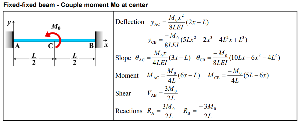
Formula
| Quantity | Formula |
|---|---|
| Deflection (AC) | \( y_{AC} = \frac{M_0 x^2}{8 L E I} (2x - L) \) |
| Deflection (CB) | \( y_{CB} = -\frac{M_0}{8 L E I} \left(5Lx^2 - 2x^3 - 4L^2x + L^3\right) \) |
| Slope (AC) | \( \theta_{AC} = \frac{M_0 x}{4 L E I} (3x - L) \) |
| Slope (CB) | \( \theta_{CB} = -\frac{M_0}{8 L E I} \left(10Lx - 6x^2 - 4L^2\right) \) |
| Moment (AC) | \( M_{AC} = \frac{M_0}{4 L} (6x - L) \) |
| Moment (CB) | \( M_{CB} = -\frac{M_0}{4 L} (5L - 6x) \) |
| Shear | \( V_{AB} = \frac{3 M_0}{2 L} \) |
| Reaction (RA) | \( R_A = \frac{3 M_0}{2 L} \) |
| Reaction (RB) | \( R_B = -\frac{3 M_0}{2 L} \) |
Definitions
| Symbol | Physical quantity | Units |
|---|---|---|
| E·I | Flexural rigidity | N·m², Pa·m⁴ |
| y | Deflection or deformation | m |
| θ | Slope, Angle of rotation | - |
| x | Distance from support (origin) | m |
| L | Length of beam (without overhang) | m |
| M | Moment, Bending moment, Couple moment applied | N·m |
| P | Concentrated load, Point load, Concentrated force | N |
| w | Distributed load, Load per unit length | N/m |
| R | Reaction load, reaction force | N |
| V | Shear force, shear | N |