 Home
Home Back
BackCantilever beam - Uniformly distributed load Calculator
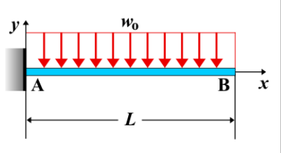
Cantilever Beam - Uniformly Distributed Load
A cantilever beam is a structural element that is fixed at one end and free at the other. When a uniformly distributed load is applied across the entire length of the beam, it causes varying shear force, bending moment, and deflection along the beam. In this case, the load intensity is constant over the full span of the beam.
Key Concepts
- Uniformly Distributed Load: A constant load intensity, \( w \), applied uniformly across the entire length of the beam. The load distribution remains the same throughout the length of the beam.
- Fixed End: The end of the beam that is rigidly attached to a support, preventing both rotation and translation.
- Free End: The unsupported end of the beam, where the beam is free to move and no load is applied.
- Shear Force: The shear force increases linearly along the length of the beam, with the maximum shear force occurring at the fixed end.
- Bending Moment: The bending moment increases quadratically along the length of the beam and reaches its maximum at the fixed end.
- Deflection: The deflection increases along the beam, with the maximum deflection occurring at the free end, influenced by the uniform load applied across the beam.
Behavior of the Cantilever Beam
- Reaction Forces:
- At the fixed end, the total equivalent load from the uniform load is equal to \( w \cdot L \), where \( w \) is the load intensity and \( L \) is the length of the beam.
- A reaction moment \( M_A \) is generated at the fixed end to counteract the effect of the applied load.
- Shear Force Diagram:
- The shear force increases linearly from the free end to the fixed end of the beam.
- The maximum shear force occurs at the fixed end and is given by \( V_A = w \cdot L \).
- Bending Moment Diagram:
- The bending moment increases quadratically along the beam and reaches its maximum at the fixed end.
- The maximum bending moment at the fixed end is given by \( M_A = \frac{w \cdot L^2}{2} \).
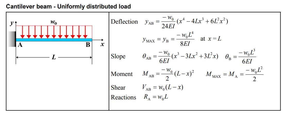
- Deflection: The deflection at the free end of the beam is influenced by the uniform load intensity and the length of the beam. The deflection can be calculated using the standard deflection formula for a uniformly loaded cantilever beam: \[ \delta_{\text{max}} = \frac{w \cdot L^4}{8EI} \] where \( E \) is the modulus of elasticity and \( I \) is the moment of inertia of the beam's cross-section.
Applications
- Structural Engineering: Common in beams subjected to loads from their own weight or from uniformly distributed loads, such as floors, bridges, and beams in buildings.
- Mechanical Systems: Found in components where the load is uniformly applied, such as machine frames, supports, or conveyor systems.
- Construction: Used in analyzing cantilevered beams in construction that carry uniform loads, such as walls or roofs supported at one end.
Formula
| Category | Formula |
|---|---|
| Deflection (\( y_{AB} \)) | \[ y_{AB} = \frac{-w_0}{24EI}(x^4 - 4Lx^3 + 6L^2x^2) \] |
| Maximum Deflection (\( y_{\text{MAX}} = y_B \)) | \[ y_{\text{MAX}} = y_B = \frac{-w_0 L^4}{8EI} \quad \text{at } x = L \] |
| Slope (\( \theta_{AB} \)) | \[ \theta_{AB} = \frac{-w_0}{6EI}(x^3 - 3Lx^2 + 3L^2x) \] |
| Slope at B (\( \theta_B \)) | \[ \theta_B = \frac{-w_0 L^3}{6EI} \] |
| Moment (\( M_{AB} \)) | \[ M_{AB} = \frac{-w_0}{2}(L - x)^2 \] |
| Maximum Moment (\( M_{\text{MAX}} = M_A \)) | \[ M_{\text{MAX}} = M_A = \frac{-w_0 L^2}{2} \] |
| Shear (\( V_{AB} \)) | \[ V_{AB} = w_0(L - x) \] |
| Reactions (\( R_A \)) | \[ R_A = w_0 L \] |
Definitions
| Symbol | Physical quantity | Units |
|---|---|---|
| E·I | Flexural rigidity | N·m², Pa·m⁴ |
| y | Deflection or deformation | m |
| θ | Slope, Angle of rotation | - |
| x | Distance from support (origin) | m |
| L | Length of beam (without overhang) | m |
| M | Moment, Bending moment, Couple moment applied | N·m |
| P | Concentrated load, Point load, Concentrated force | N |
| w | Distributed load, Load per unit length | N/m |
| R | Reaction load, reaction force | N |
| V | Shear force, shear | N |