 Home
Home Back
BackCantilever beam - Uniform load partially distributed at fixed end Calculator
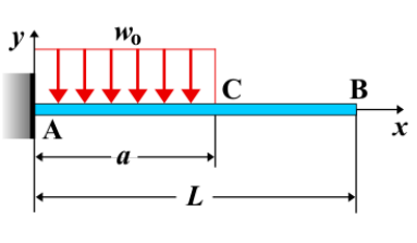
Cantilever Beam - Uniform Load Partially Distributed at Fixed End
A cantilever beam is a structural element that is fixed at one end and free at the other. When a **uniformly distributed load** is applied only to the part of the beam near the fixed end, it generates a different response compared to a load applied over the entire length. This partially distributed load causes varying shear force, bending moment, and deflection along the beam.
Key Concepts
- Uniform Load: A distributed load that is constant along the length of the beam section it is applied to. It acts with the same intensity throughout the part of the beam, denoted as \( w \), over a length \( a \) from the fixed end.
- Fixed End: The end of the beam that is rigidly attached to a support, preventing both rotation and translation.
- Free End: The unsupported end of the beam, where the load intensity is zero.
- Shear Force: The shear force varies along the beam, with a sudden change at the end of the distributed load region.
- Bending Moment: The bending moment increases at a linear rate in the region under the uniform load and then remains constant after the load ends.
- Deflection: The deflection is more pronounced near the fixed end, where the load is applied, and the maximum deflection occurs closer to the free end.
Behavior of the Cantilever Beam
- Reaction Forces:
- At the fixed end, the total equivalent load from the uniform load is equal to \( w \cdot a \), where \( w \) is the load intensity and \( a \) is the length of the uniformly loaded section.
- A reaction moment \( M_A \) is developed to balance the effect of the applied load over the fixed part of the beam.
- Shear Force Diagram:
- The shear force diagram shows a constant shear force over the length of the applied load region, followed by a sudden drop after the uniform load ends.
- The maximum shear force occurs at the fixed end, and is given by \( V_A = w \cdot a \).
- Bending Moment Diagram:
- The bending moment increases linearly under the uniformly distributed load, reaching a maximum value at the fixed end.
- Once the uniformly distributed load ends, the bending moment remains constant until the free end of the beam.
- The maximum bending moment at the fixed end is \( M_A = \frac{w \cdot a^2}{2} \).
- Deflection: The deflection at the free end is determined by the properties of the beam, and it is affected by both the uniform load and the beam's material and geometry. The maximum deflection typically occurs closer to the free end and can be calculated using the formula for deflection due to a uniform load: \[ \delta_{\text{max}} = \frac{w \cdot a^4}{8EI} \] where \( E \) is the modulus of elasticity and \( I \) is the moment of inertia of the beam's cross-section.
Applications
- Structural Engineering: Common in beams with loads applied near the supports, such as floor beams with concentrated equipment or machinery near one end.
- Mechanical Systems: Found in situations where a component has a localized load, like brackets or frames supporting equipment.
- Construction: Used to analyze beams subjected to localized loads, such as those from partitions or columns attached near the fixed end of a beam.
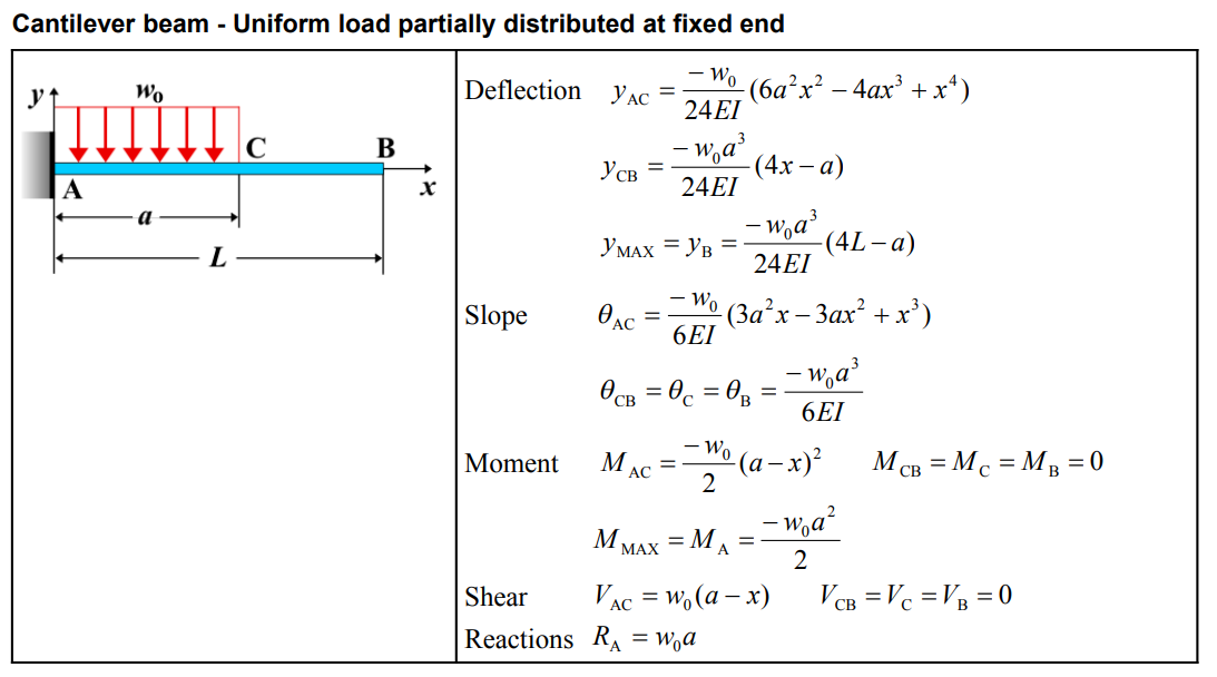
Formula
| Category | Formula |
|---|---|
| Deflection (\( y_{AC} \)) | \[ y_{AC} = \frac{-w_0}{24EI} \left( 6a^2x^2 - 4ax^3 + x^4 \right) \] |
| Deflection (\( y_{CB} \)) | \[ y_{CB} = \frac{-w_0a^3}{24EI} (4x - a) \] |
| Maximum Deflection (\( y_{\text{MAX}} = y_B \)) | \[ y_{\text{MAX}} = y_B = \frac{-w_0a^3}{24EI}(4L - a) \] |
| Slope (\( \theta_{AC} \)) | \[ \theta_{AC} = \frac{-w_0}{6EI}(3a^2x - 3ax^2 + x^3) \] |
| Slope (\( \theta_{CB} = \theta_C = \theta_B \)) | \[ \theta_{CB} = \theta_C = \theta_B = \frac{-w_0a^3}{6EI} \] |
| Moment (\( M_{AC} \)) | \[ M_{AC} = \frac{-w_0}{2}(a - x)^2 \] |
| Moment (\( M_{CB} = M_C = M_B \)) | \[ M_{CB} = M_C = M_B = 0 \] |
| Maximum Moment (\( M_{\text{MAX}} = M_A \)) | \[ M_{\text{MAX}} = M_A = \frac{-w_0a^2}{2} \] |
| Shear (\( V_{AC} \)) | \[ V_{AC} = w_0(a - x) \] |
| Shear (\( V_{CB} = V_C = V_B \)) | \[ V_{CB} = V_C = V_B = 0 \] |
| Reaction (\( R_A \)) | \[ R_A = w_0a \] |
Definitions
| Symbol | Physical quantity | Units |
|---|---|---|
| E·I | Flexural rigidity | N·m², Pa·m⁴ |
| y | Deflection or deformation | m |
| θ | Slope, Angle of rotation | - |
| x | Distance from support (origin) | m |
| L | Length of beam (without overhang) | m |
| M | Moment, Bending moment, Couple moment applied | N·m |
| P | Concentrated load, Point load, Concentrated force | N |
| w | Distributed load, Load per unit length | N/m |
| R | Reaction load, reaction force | N |
| V | Shear force, shear | N |