 Home
Home Back
BackCantilever beam - Load increasing uniformly to free end Calculator
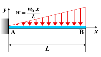
Cantilever Beam - Load Increasing Uniformly to Free End
A cantilever beam is a structural element that is fixed at one end and free at the other. In this case, a **linearly increasing distributed load** is applied, where the load intensity begins at zero at the fixed end and increases towards the free end. This kind of load distribution causes varying shear force, bending moment, and deflection along the length of the beam.
Key Concepts
- Linearly Increasing Load: The load increases in a linear manner from zero at the fixed end to a maximum value \( w_0 \) at the free end. The load intensity is given by \( w(x) = w_0 \frac{x}{L} \), where \( L \) is the length of the beam and \( x \) is the distance from the fixed end.
- Fixed End: The end of the beam that is rigidly attached to a support, preventing both rotation and translation.
- Free End: The unsupported end of the beam, where the load intensity is maximum and the beam is free to move.
- Shear Force: The shear force varies along the beam due to the increasing load intensity, and it tends to decrease as the load increases from the fixed to the free end.
- Bending Moment: The bending moment is generated by the increasing load, and it increases at a quadratic rate along the beam's length, reaching its maximum at the fixed end.
- Deflection: The deflection of the beam increases from the fixed end to the free end, and the maximum deflection occurs at the free end.
Behavior of the Cantilever Beam
- Reaction Forces:
- At the fixed end, the total equivalent load acts as a concentrated force of magnitude \( \frac{w_0 L}{2} \).
- A reaction moment \( M_A \) is developed to counteract the distributed load.
- Shear Force Diagram:
- The shear force follows a quadratic variation along the beam.
- The maximum shear force occurs at the fixed end and is given by \( V_A = \frac{w_0 L}{2} \).
- Bending Moment Diagram:
- The bending moment increases cubically along the beam.
- The maximum moment at the fixed end is given by \( M_A = \frac{w_0 L^2}{6} \).
- Deflection: The deflection at the free end is given by: \[ \delta_{\text{max}} = \frac{w_0 L^4}{30EI} \] where \( E \) is the modulus of elasticity and \( I \) is the moment of inertia of the beam's cross-section.
Applications
- Structural Engineering: Common in scenarios where beams experience loads that increase from the fixed end to the free end, such as beams under varying pressure conditions like wind or soil pressure.
- Mechanical Systems: Found in applications where parts are subjected to loads that increase along their length, like turbine blades or machine components.
- Construction: Used in the analysis of cantilevered structures that experience varying loads, such as beams carrying varying self-weight along their span.
Formula
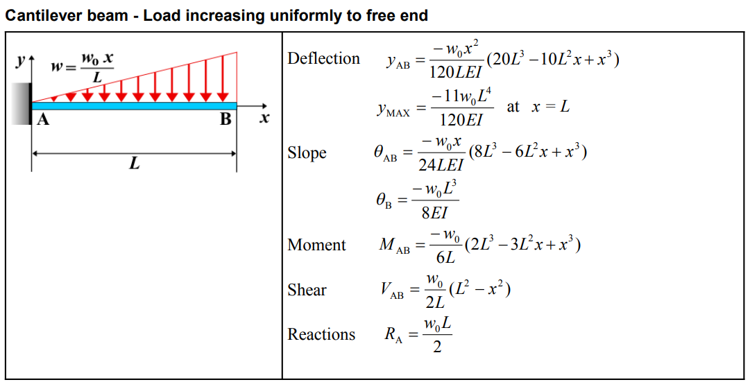
| Parameter | Formula |
|---|---|
| Deflection (\(y_{AB}\)) | \(-\frac{w_0 x^2}{120LEI} (20L^3 - 10L^2x + x^3)\) |
| Maximum Deflection (\(y_{MAX}\)) | \(-\frac{11w_0 L^4}{120EI}\) at \(x = L\) |
| Slope (\(\theta_{AB}\)) | \(-\frac{w_0 x}{24LEI} (8L^3 - 6L^2x + x^3)\) |
| Slope at B (\(\theta_B\)) | \(-\frac{w_0 L^3}{8EI}\) |
| Moment (\(M_{AB}\)) | \(-\frac{w_0}{6L} (2L^3 - 3L^2x + x^3)\) |
| Shear (\(V_{AB}\)) | \(\frac{w_0}{2L} (L^2 - x^2)\) |
| Reactions (\(R_A\)) | \(\frac{w_0 L}{2}\) |
Definitions
| Symbol | Physical quantity | Units |
|---|---|---|
| E·I | Flexural rigidity | N·m², Pa·m⁴ |
| y | Deflection or deformation | m |
| θ | Slope, Angle of rotation | - |
| x | Distance from support (origin) | m |
| L | Length of beam (without overhang) | m |
| M | Moment, Bending moment, Couple moment applied | N·m |
| P | Concentrated load, Point load, Concentrated force | N |
| w | Distributed load, Load per unit length | N/m |
| R | Reaction load, reaction force | N |
| V | Shear force, shear | N |