 Home
Home Back
BackCantilever beam - Load increasing uniformly to fixed end Calculator
Cantilever Beam - Load Increasing Uniformly to Fixed End
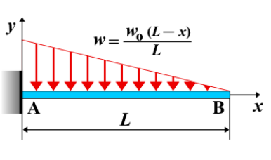
A cantilever beam is a structural element fixed at one end and free at the other. When a linearly increasing distributed load is applied along the beam, with the load intensity increasing from zero at the free end to a maximum \( w_0 \) at the fixed end, it creates varying shear force, bending moment, and deflection along the beam.
Key Concepts
- Linearly Increasing Load: A distributed load that starts from zero at the free end and increases to \( w_0 \) at the fixed end, expressed as \( w(x) = w_0 \frac{x}{L} \), where \( L \) is the beam length.
- Fixed End: The end rigidly attached to a support, resisting both rotation and translation.
- Free End: The unsupported end where the load intensity is zero.
- Shear Force: Varies non-linearly along the beam due to the gradually increasing load.
- Bending Moment: The moment increases more rapidly near the fixed end, reaching a maximum at that point.
- Deflection: The maximum deflection occurs at the free end and follows a curved shape due to the varying load.
Behavior of the Cantilever Beam
- Reaction Forces:
- At the fixed end, the total equivalent load acts as a concentrated force of magnitude \( \frac{w_0 L}{2} \).
- A reaction moment \( M_A \) is developed to counteract the distributed load.
- Shear Force Diagram:
- The shear force follows a quadratic variation along the beam.
- The maximum shear force occurs at the fixed end and is given by \( V_A = \frac{w_0 L}{2} \).
- Bending Moment Diagram:
- The bending moment increases cubically along the beam.
- The maximum moment at the fixed end is given by \( M_A = \frac{w_0 L^2}{6} \).
- Deflection: The deflection at the free end is given by: \[ \delta_{\text{max}} = \frac{w_0 L^4}{30EI} \] where \( E \) is the modulus of elasticity and \( I \) is the moment of inertia of the beam cross-section.
Applications
- Structural Engineering: Common in beams subjected to wind pressure or soil pressure.
- Mechanical Systems: Found in components experiencing variable loading, such as machine parts and turbine blades.
- Construction: Used in analysis of cantilevered structures under self-weight and other non-uniform loads.
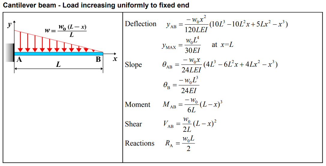
Formula
| Parameter | Formula |
|---|---|
| Deflection (\(y_{AB}\)) | \(-\frac{w_0 x^2}{120LEI} (10L^3 - 10L^2x + 5Lx^2 - x^3)\) |
| Maximum Deflection (\(y_{MAX}\)) | \(\frac{w_0 L^4}{30EI}\) at \(x = L\) |
| Slope (\(\theta_{AB}\)) | \(-\frac{w_0 x}{24LEI} (4L^3 - 6L^2x + 4Lx^2 - x^3)\) |
| Slope at B (\(\theta_B\)) | \(-\frac{w_0 L^3}{24EI}\) |
| Moment (\(M_{AB}\)) | \(-\frac{w_0}{6L} (L - x)^3\) |
| Shear (\(V_{AB}\)) | \(\frac{w_0}{2L} (L - x)^2\) |
| Reactions (\(R_A\)) | \(\frac{w_0 L}{2}\) |
Definitions
| Symbol | Physical quantity | Units |
|---|---|---|
| E·I | Flexural rigidity | N·m², Pa·m⁴ |
| y | Deflection or deformation | m |
| θ | Slope, Angle of rotation | - |
| x | Distance from support (origin) | m |
| L | Length of beam (without overhang) | m |
| M | Moment, Bending moment, Couple moment applied | N·m |
| P | Concentrated load, Point load, Concentrated force | N |
| w | Distributed load, Load per unit length | N/m |
| R | Reaction load, reaction force | N |
| V | Shear force, shear | N |