 Home
Home Back
BackCantilever beam - Couple moment Mo at free end Calculator
Formula
| Parameter | Formula |
|---|---|
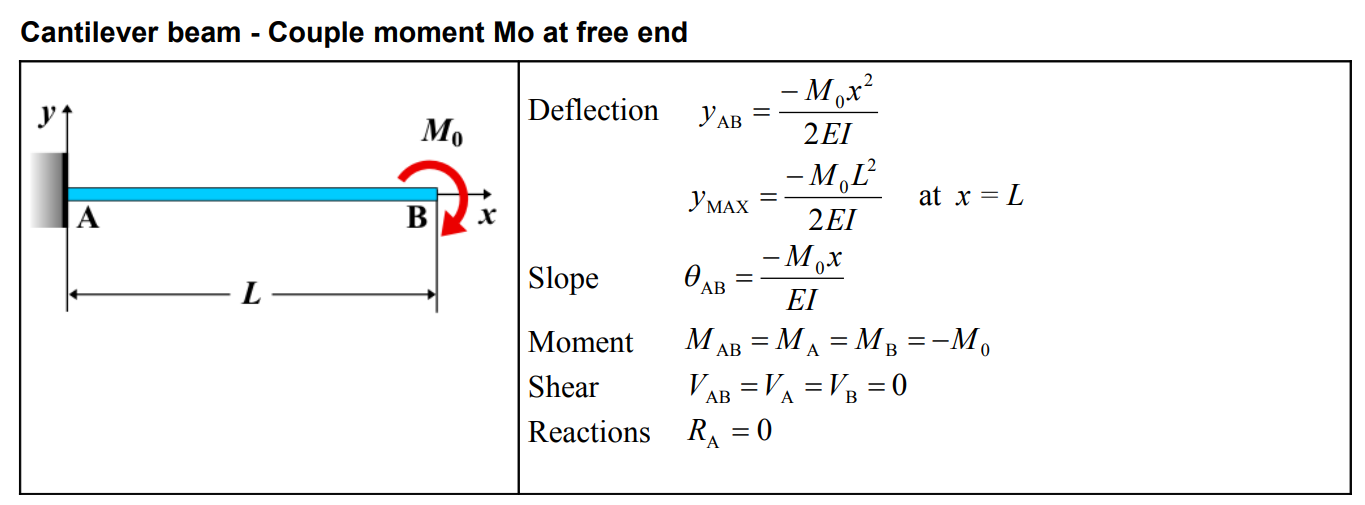
| Deflection \(y_{AB}\) | \(y_{AB} = \frac{M_0 x^2}{2EI}\) |
| Deflection at \(x = L\) (\(y_{MAx}\) for segment AB) | \(y_{MAx} = -\frac{M_0 L^2}{2EI}\) |
| Slope \(\theta_{AB}\) | \(\theta_{AB} = -\frac{M_0 x}{EI}\) |
| Moment \(M_{AB}\) (\(M_A = M_B\)) | \(M_{AB} = M_A = M_B = -M_0\) |
| Shear \(V_{AB}\) (\(V_A = V_B\)) | \(V_{AB} = V_A = V_B = 0\) |
| Reactions \(R_A\) | \(R_A = 0\) |
Cantilever Beam - Couple Moment \( M_o \) at Free End
A cantilever beam is a structural element fixed at one end and free at the other. When a couple moment \( M_o \) is applied at the free end, it induces a pure bending effect without generating shear force. This loading condition primarily influences the bending moment distribution and deflection of the beam.
Key Concepts
- Couple Moment \( M_o \): A moment (torque) applied at the free end, measured in units of force × distance (e.g., N·m or lb·ft).
- Fixed End: The end rigidly attached to a support, resisting both rotation and translation.
- Free End: The unsupported end where the moment is applied, causing rotational displacement.
- Shear Force: Zero throughout the beam since the applied couple moment does not generate a resultant force.
- Bending Moment: The moment remains constant throughout the beam, equal to \( M_o \).
- Deflection: The beam experiences angular rotation at the free end without transverse displacement.
Behavior of the Cantilever Beam
- Reaction Forces:
- At the fixed end, the beam generates a reaction moment \( M_R = M_o \) to balance the applied couple moment.
- No vertical reaction force is produced.
- Shear Force Diagram: The shear force remains zero throughout the entire length of the beam.
- Bending Moment Diagram:
- The bending moment is constant along the beam and equal to \( M_o \).
- Unlike other loading conditions, there is no variation in the moment distribution.
- Deflection: The beam undergoes rotation at the free end, calculated using: \[ \theta_{\text{max}} = \frac{M_o L}{EI} \] where \( E \) is the modulus of elasticity, \( I \) is the moment of inertia, and \( L \) is the beam length.
Applications
- Structural Engineering: Used in beams and supports subjected to pure moments at their free ends.
- Mechanical Systems: Common in robotic arms, torque shafts, and rotating cantilevered components.
- Construction: Helps analyze the effects of end moments in overhanging structures.
Definitions
| Symbol | Physical quantity | Units |
|---|---|---|
| E·I | Flexural rigidity | N·m², Pa·m⁴ |
| y | Deflection or deformation | m |
| θ | Slope, Angle of rotation | - |
| x | Distance from support (origin) | m |
| L | Length of beam (without overhang) | m |
| M | Moment, Bending moment, Couple moment applied | N·m |
| P | Concentrated load, Point load, Concentrated force | N |
| w | Distributed load, Load per unit length | N/m |
| R | Reaction load, reaction force | N |
| V | Shear force, shear | N |