 Home
Home Back
BackCantilever beam - Cosinusoidal distributed load Calculator
Cantilever Beam - Cosinusoidal Distributed Load
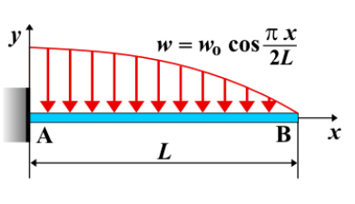
A cantilever beam is a structural element fixed at one end and free at the other. When a cosinusoidal distributed load is applied along the length of the beam, the load intensity varies following a cosine function. This type of loading commonly occurs in aerodynamic, wave, and vibration-related applications.
Key Concepts
- Cosinusoidal Distributed Load: A varying load described by \( w(x) = w_0 \cos\left(\frac{\pi x}{L}\right) \), where \( w_0 \) is the maximum load intensity at \( x = 0 \), and \( L \) is the beam length.
- Fixed End: The end rigidly attached to a support, resisting both rotation and translation.
- Free End: The unsupported end where the load intensity is minimum.
- Shear Force: Varies non-linearly along the beam due to the cosine distribution of the applied load.
- Bending Moment: The moment varies along the beam, with the maximum occurring at the fixed end.
- Deflection: The displacement of the beam, maximum at the free end, influenced by the cosinusoidal loading pattern.
Behavior of the Cantilever Beam
- Reaction Forces:
- At the fixed end, the beam generates a reaction force \( R_A \) equal to the total equivalent force of the cosinusoidal load.
- A reaction moment \( M_A \) is developed to balance the distributed load.
- Shear Force Diagram:
- The shear force is obtained by integrating the cosinusoidal load distribution.
- It varies along the beam, reaching its maximum at the fixed end.
- Bending Moment Diagram:
- Calculated by integrating the shear force distribution.
- The maximum bending moment occurs at the fixed end, and it follows a complex non-linear distribution.
- Deflection: Maximum at the free end, derived using beam deflection formulas for varying loads.
Applications
- Aerodynamics: Modeling aerodynamic loads on wings and blades.
- Wave Loading: Used in offshore structures subject to wave-induced forces.
- Structural Engineering: Analysis of beams subjected to gradually varying loads.
Formula
| Quantity | Formula |
|---|---|
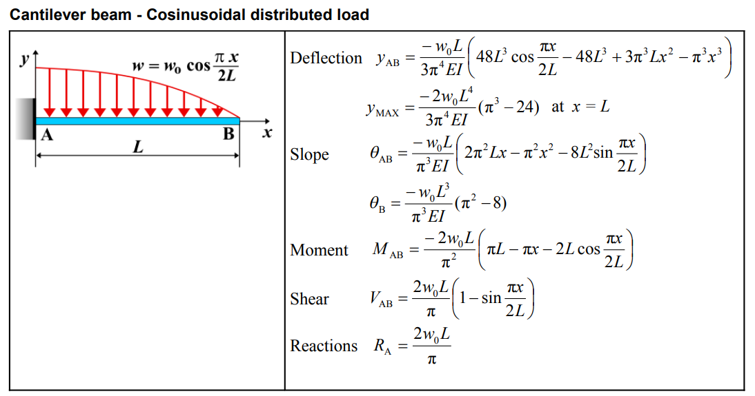
| Deflection \(y_{AB}\) | \[ y_{AB} = \frac{-w_0 L}{3\pi^4 EI} \left( 48L^3 \cos \frac{\pi x}{2L} - 48L^3 + 3\pi^3 Lx^2 - \pi^3 x^3 \right) \] |
| Maximum Deflection \(y_{MAX}\) | \[ y_{MAX} = \frac{-2w_0 L^4}{3\pi^4 EI} (\pi^3 - 24) \quad \text{at } x = L \] |
| Slope \(\theta_{AB}\) | \[ \theta_{AB} = \frac{-w_0 L}{\pi^3 EI} \left( 2\pi^2 Lx - \pi^2 x^2 - 8L^2 \sin \frac{\pi x}{2L} \right) \] |
| Slope at B \(\theta_B\) | \[ \theta_B = \frac{-w_0 L^3}{\pi^3 EI} (\pi^2 - 8) \] |
| Moment \(M_{AB}\) | \[ M_{AB} = \frac{-2w_0 L}{\pi^2} \left( \pi L - \pi x - 2L \cos \frac{\pi x}{2L} \right) \] |
| Shear \(V_{AB}\) | \[ V_{AB} = \frac{2w_0 L}{\pi} \left( 1 - \sin \frac{\pi x}{2L} \right) \] |
| Reactions \(R_A\) | \[ R_A = \frac{2w_0 L}{\pi} \] |
Definitions
| Symbol | Physical quantity | Units |
|---|---|---|
| E·I | Flexural rigidity | N·m², Pa·m⁴ |
| y | Deflection or deformation | m |
| θ | Slope, Angle of rotation | - |
| x | Distance from support (origin) | m |
| L | Length of beam (without overhang) | m |
| M | Moment, Bending moment, Couple moment applied | N·m |
| P | Concentrated load, Point load, Concentrated force | N |
| w | Distributed load, Load per unit length | N/m |
| R | Reaction load, reaction force | N |
| V | Shear force, shear | N |