 Home
Home Back
BackCantilever beam - Concentrated load P at free end Calculator
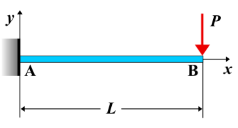
Cantilever Beam - Concentrated Load \( P \) at Free End
A cantilever beam is a structural element fixed at one end and free at the other. When a concentrated load \( P \) is applied at the free end, it induces shear force, bending moment, and deflection along the beam. This is a common loading condition that results in the maximum possible deflection and bending moment at the fixed support.
Key Concepts
- Concentrated Load \( P \): A single force applied at the free end of the beam, measured in units of force (e.g., N or lb).
- Fixed End: The end rigidly attached to a support, resisting both rotation and translation.
- Free End: The unsupported end where the load is applied, experiencing the maximum deflection.
- Shear Force: Constant along the entire length of the beam.
- Bending Moment: Varies linearly along the beam, reaching its maximum at the fixed end.
- Deflection: Maximum at the free end, causing the beam to bend downward.
Behavior of the Cantilever Beam
- Reaction Forces:
- At the fixed end, the beam generates a reaction force \( R_A = P \) to balance the external load.
- A reaction moment \( M_A = P \cdot L \) is developed, where \( L \) is the length of the beam.
- Shear Force Diagram:
- The shear force remains constant and equal to \( P \) throughout the entire beam.
- Bending Moment Diagram:
- The bending moment varies linearly from zero at the free end to a maximum of \( M_A = P \cdot L \) at the fixed end.
- Deflection: Maximum at the free end, calculated using the formula: \[ \delta_{\text{max}} = \frac{P L^3}{3EI} \] where \( E \) is the modulus of elasticity and \( I \) is the moment of inertia of the beam cross-section.
Applications
- Structural Engineering: Common in overhanging balconies, diving boards, and cantilevered beams in buildings.
- Mechanical Systems: Used in robotic arms, levers, and crane booms.
- Construction: Helps determine the deflection and bending moment for designing safe cantilever structures.
Formula
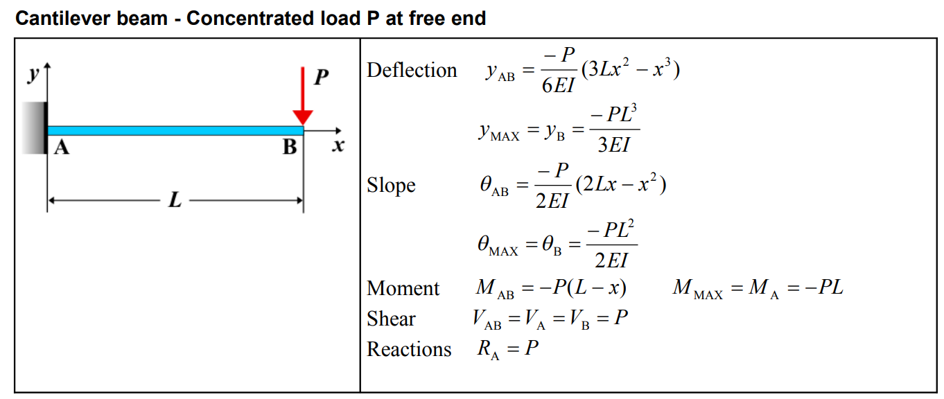
| Deflection \(y\) | \(y_{AB} = \frac{6EI}{-P} (3Lx^2 - x^3)\) | \(y_{MAx} = y_B = -\frac{PL^3}{3EI}\) |
| Slope \(\theta\) | \(\theta_{AB} = -\frac{P}{2EI} (2Lx - x^2)\) | \(\theta_{MAx} = \theta_B = -\frac{PL^2}{2EI}\) |
| Moment \(M\) | \(M_{AB} = -P(L - x)\) | \(M_{MAx} = M_A = -PL\) |
| Shear \(V\) | \(V_{AB} = V_A = V_B = P\) | |
| Reactions \(R\) | \(R_A = P\) | |
Definitions
| Symbol | Physical quantity | Units |
|---|---|---|
| E·I | Flexural rigidity | N·m², Pa·m⁴ |
| y | Deflection or deformation | m |
| θ | Slope, Angle of rotation | - |
| x | Distance from support (origin) | m |
| L | Length of beam (without overhang) | m |
| M | Moment, Bending moment, Couple moment applied | N·m |
| P | Concentrated load, Point load, Concentrated force | N |
| w | Distributed load, Load per unit length | N/m |
| R | Reaction load, reaction force | N |
| V | Shear force, shear | N |