 Home
Home Back
BackCantilever beam - Concentrated load P at any point Calculator
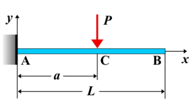
Cantilever Beam - Concentrated Load \( P \) at Any Point
A cantilever beam is a structural element fixed at one end and free at the other. When a concentrated load \( P \) is applied at any point along the beam, it induces specific effects such as shear force, bending moment, and deflection. Unlike a couple moment, a concentrated load generates both a reaction force and a bending moment at the fixed support.
Key Concepts
- Concentrated Load \( P \): A single force applied at a specific point along the beam, measured in units of force (e.g., N or lb).
- Fixed End: The end rigidly attached to a support, resisting both rotation and translation.
- Free End: The unsupported end that experiences maximum deflection due to the applied force.
- Shear Force: Abruptly changes at the point of load application, influencing the shear force diagram.
- Bending Moment: Varies along the beam, with the maximum moment occurring at the fixed end.
- Deflection: The displacement of the beam, dependent on the load position and magnitude.
Behavior of the Cantilever Beam
- Reaction Forces:
- At the fixed end, the beam generates a reaction force \( R_A = P \) to balance the external load.
- A reaction moment \( M_A = P \cdot a \) is developed, where \( a \) is the distance from the fixed end to the applied load.
- Shear Force Diagram:
- Shear force remains constant between the fixed end and the point of load application.
- At the point of application, the shear force decreases abruptly by \( P \).
- Beyond the load application point, the shear force remains zero.
- Bending Moment Diagram:
- Decreases linearly from the fixed end to the point of load application.
- The maximum bending moment at the fixed end is \( M_A = P \cdot a \).
- Beyond the load application point, the bending moment decreases to zero at the free end.
- Deflection: Maximum at the free end, calculated using beam deflection formulas.
Applications
- Structural Engineering: Used in bridges, balconies, and overhanging beams in buildings.
- Mechanical Systems: Applied in robotic arms, levers, and cantilevered machine components.
- Construction: Helps determine the load-bearing capacity and stability of cantilevered structures.
Formula
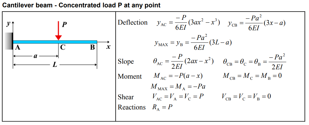
| Deflection \(y\) | \(y_{AC} = \frac{6EI}{-P} (3ax^2 - x^3)\) | \(y_{CB} = \frac{6EI}{-Pa^2} (a-x)^2(3x-a)\) |
| Deflection at \(x = L\) (\(y_{MAx} = y_B\)) | \(y_{MAx} = y_B = -\frac{Pa^2}{6EI}(3L-a)\) | |
| Slope \(\theta\) | \(\theta_{AC} = -\frac{P}{2EI}(2ax - x^2)\) | \(\theta_{CB} = \theta_C = \theta_B = -\frac{Pa^2}{2EI}\) |
| Moment \(M\) | \(M_{AC} = -P(a-x)\) | \(M_{CB} = M_C = M_B = 0\) |
| Moment at \(x = a\) (\(M_{MAx} = M_A\)) | \(M_{MAx} = M_A = -Pa\) | |
| Shear \(V\) | \(V_{AC} = V_A = V_C = P\) | \(V_{CB} = V_C = V_B = 0\) |
| Reactions \(R\) | \(R_A = P\) | |
Definitions
| Symbol | Physical quantity | Units |
|---|---|---|
| E·I | Flexural rigidity | N·m², Pa·m⁴ |
| y | Deflection or deformation | m |
| θ | Slope, Angle of rotation | - |
| x | Distance from support (origin) | m |
| L | Length of beam (without overhang) | m |
| M | Moment, Bending moment, Couple moment applied | N·m |
| P | Concentrated load, Point load, Concentrated force | N |
| w | Distributed load, Load per unit length | N/m |
| R | Reaction load, reaction force | N |
| V | Shear force, shear | N |